 Tweet
Tweet
Edit - June 2017: Public URL's to view system output and weather station:
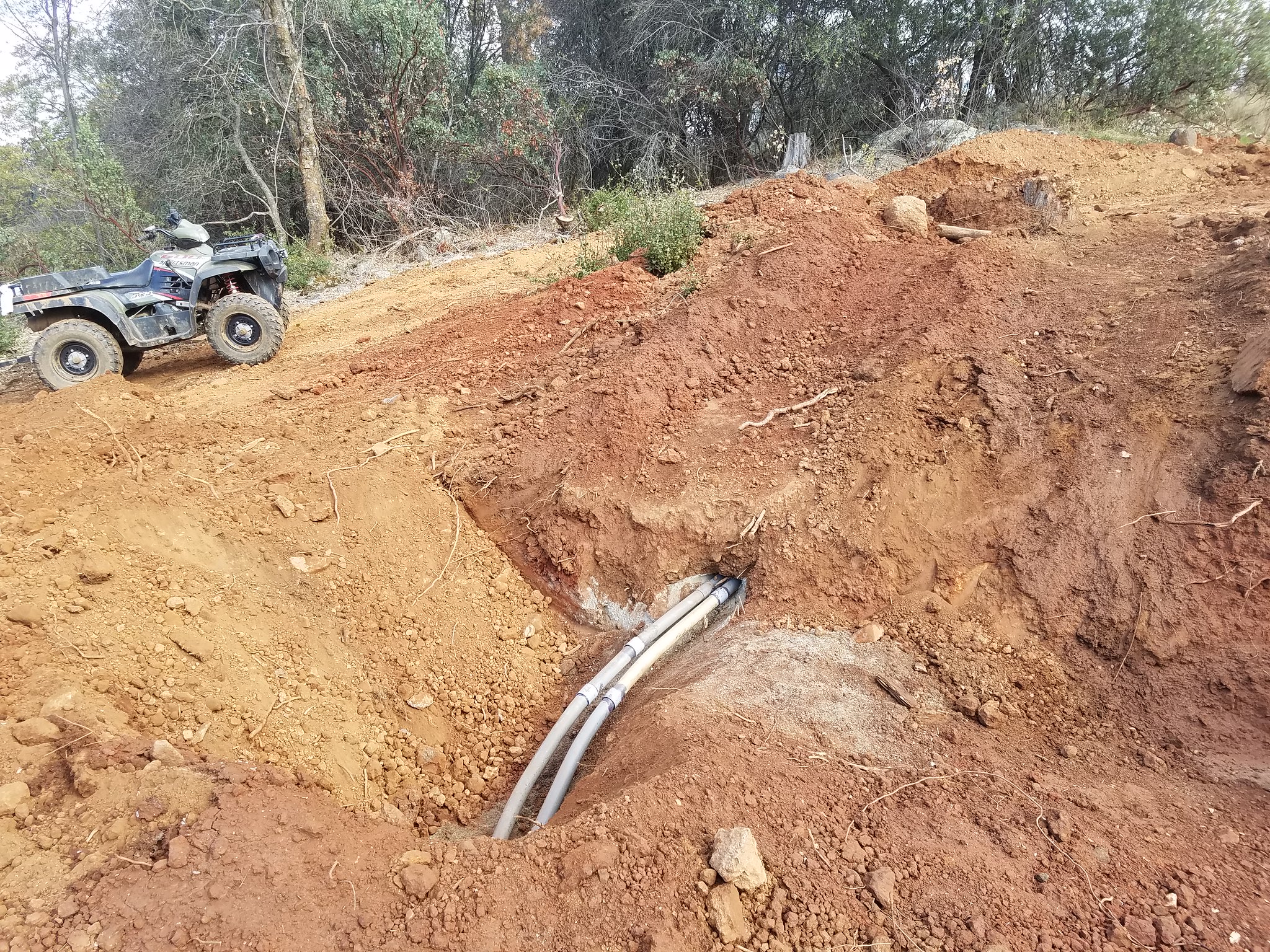
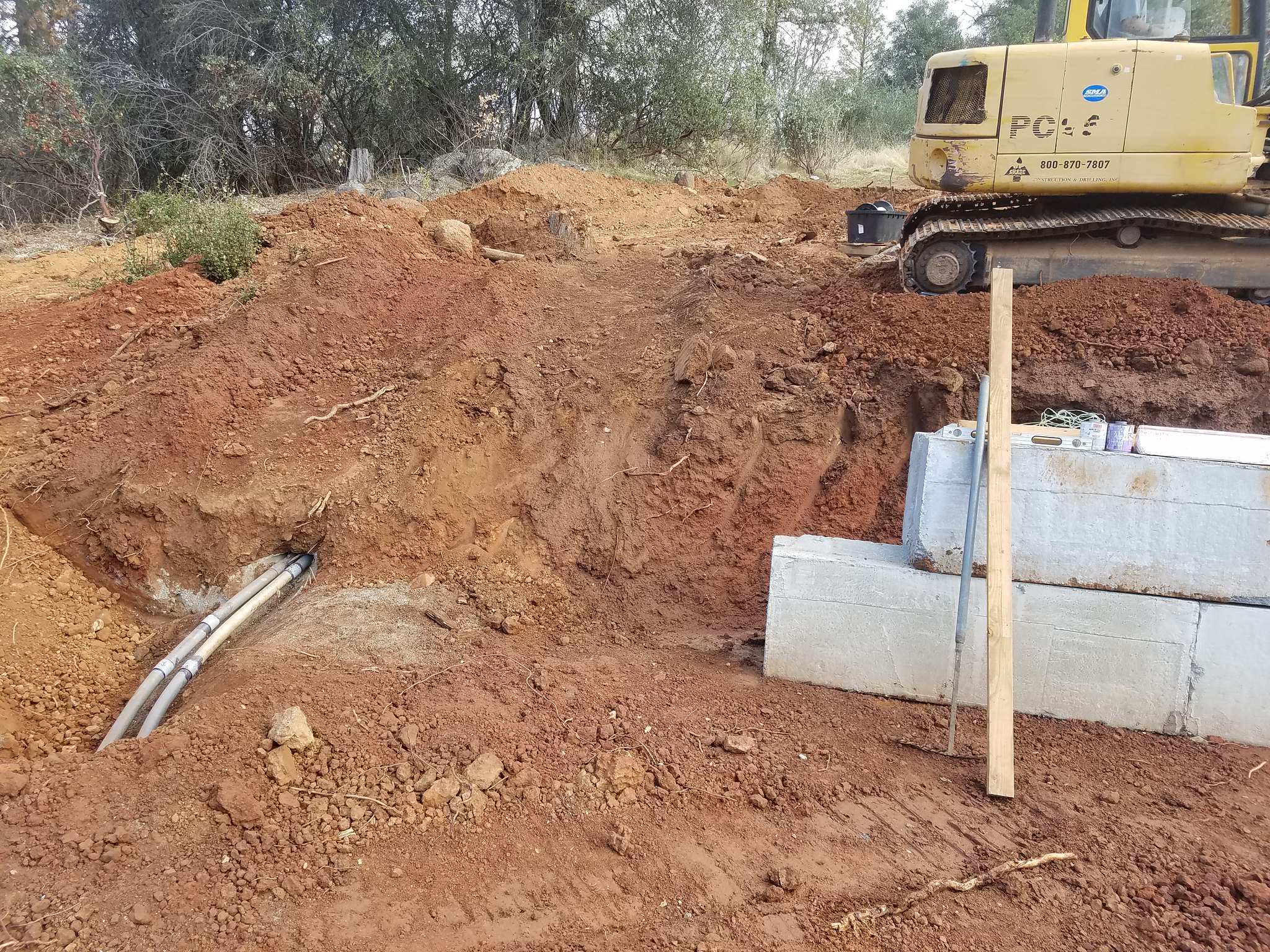
Summary - building an 80 panel ground mount microinverter grid tie system. Many unique aspects - the most significant is the location which is about 400' from the house and at least 40' lower in elevation. Very poor access complicates just about every aspect - 4WD only down there. Significant excavation needed to deal with grade and it required breaking up the system into four mounts. System is on a hillside that slopes West South West downhill over 20 degrees. System is fully permitted and I am complying with all local and state codes. Also uncommon is the entire system is implementing an NFPA 780 lightning protection system including a ground ring electrode made up of some 610' of class 1 conductor underground of which 520' is more than 30" underground. This is an owner build system, with a licensed electrician reviewing electrical work (required by local codes) and a licensed excavation contractor performing most of the ground work - trenching, filling, excavation and erosion control. This guy is an artist with his equipment and is a friend. Helps to be a Scoutmaster - you meet many parents with amazing skills.
The ground mount system is an Iron Ridge framework based on 3" schedule 40 galvanized pipe for structure and Iron Ridge rails and mounting hardware. Micro inverters are Enphase M250. Panels are Astronergy 260W panels.
The system is sized for our usage which is very large compared to most families - large home, lots of children of all ages, foster parents, well system and water storage, pool, wine cellar, huge refrigerators and the largest draw of all - my computer systems for work that run doing simulations and builds 24/7. My office is never cold in the winter - warmest room in the house. The home is new as of 2005 and itself is energy efficient - well insulated, etc. It is the computers that are killing us - these are not little things but large power hungry workstations and server - but its either that or I have to work in San Francisco - so we pay PG&E dearly so I can work at home.
Because the system is so far from the house service one of the biggest issues for micro inverter systems is voltage drop - Enphase wants you to limit the total losses from wires to 2% but that is not a spec but a guideline. I am able to stay under that 2% from the furthest microinverters all the way to the service meter by oversizing wire - the main run of about 400' is parallel runs of 4/0 and all wires on the mounts is #6. Enphase is center-tied to remove the losses from that #12 cable as much as possible.
I have been keeping a running blog on google blogger but out of respect for this forum I will not post that address - if you want to see it look at my profile. But will repost pics and comments here since I hope that some of you may find the process interesting - I am sure learning a lot especially from my mistakes. When I started this process I dove into the NEC electrical code and am trying my very best to treat it as a minimum set of standards and exceed it - especially when related to the issues you learn from NFPA 780. I cannot stress enough if you are considering owner install solar to get a copy of the NFPA 70 (NEC) and study it. Even if you don't do it yourself, you will better understand the rules that will apply to the electrical part of your system.
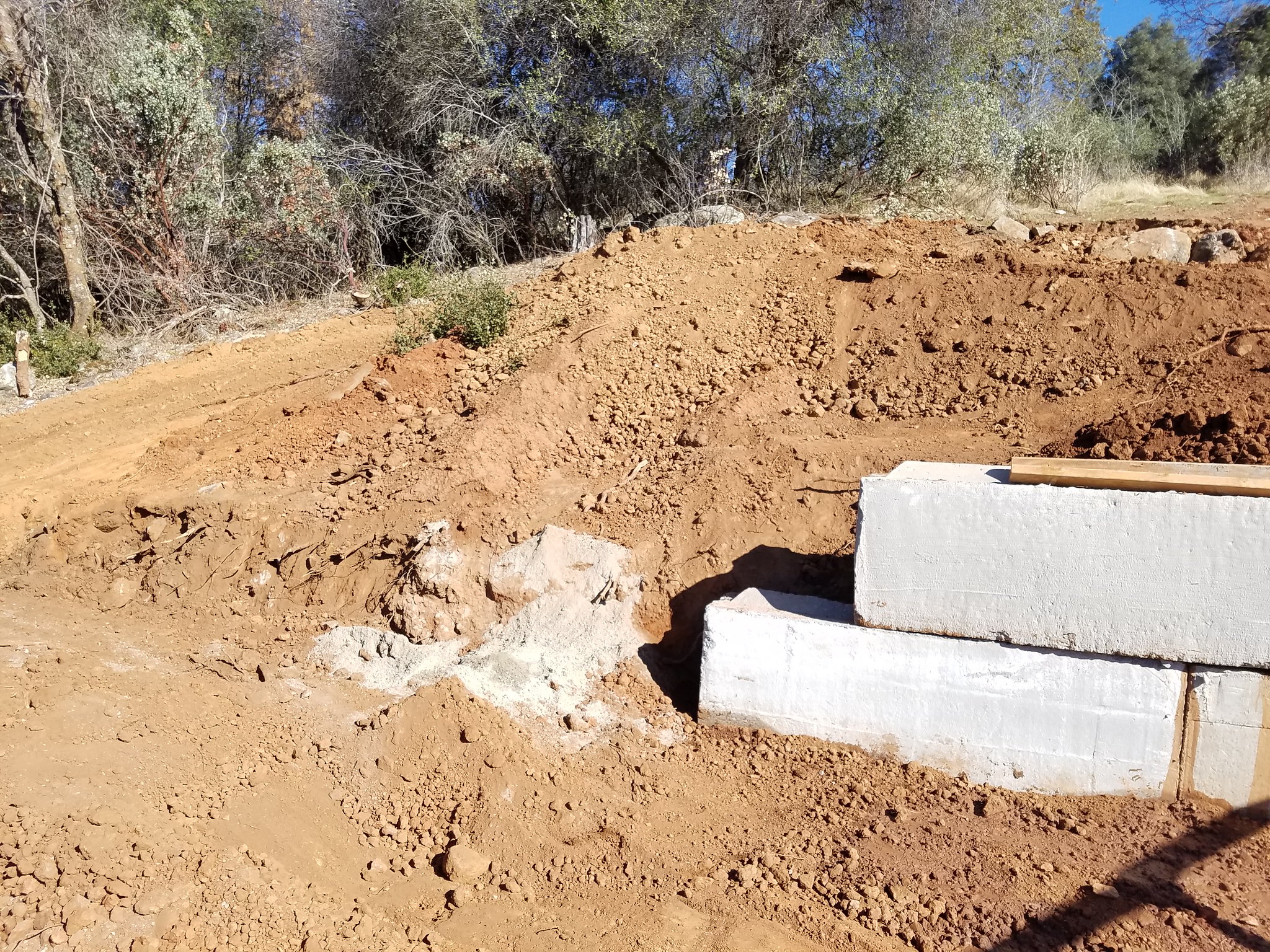
Current overall status. First inspection passed. Trenches filled, concrete poured, mount framing removed, long run of wire pulled, solar subpanel installed, 1/2 of the rails installed and erosion retaining wall in progress. Wow, can't believe I just summed up 5 months of work in a single sentence.
I have placed all my photos on a shared Google album but will repost new relevant ones on this forum. https://goo.gl/photos/6XP3sCnMjN6yhWd16 (hope I got the sharing correct).
Latest status.
Mounts 2, 3 and 4 have a smaller junction box that simply combines the five 3/4" EMT into a 2" EMT that runs underground (via 2" PVC) to mount 1. I finally finished the three junction boxes.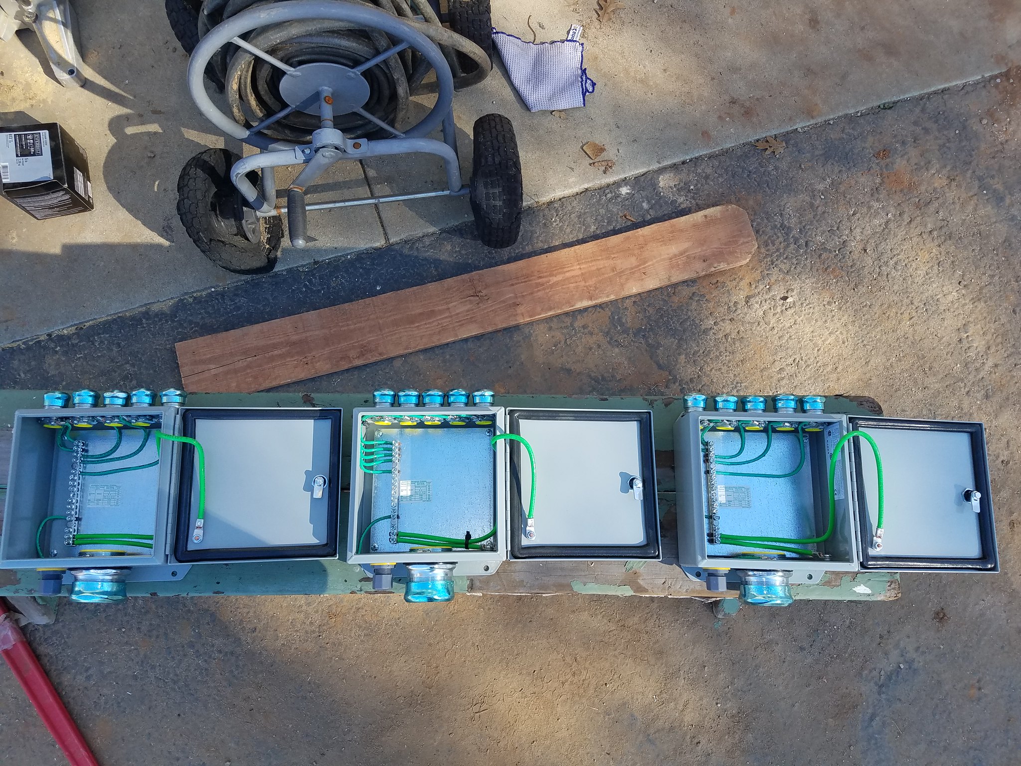
They are all the same but one (the first one I did - center) I equal spaced the EMT connectors and that was a mistake since those connectors are very close together. This will make connecting the EMT to those connectors harder. The remaining two I had the outside EMT's close the edge and then equal spaced the inside three giving must more spacing between them. The plastic water tight strain relief next to the 2" EMT is where a #6 bare EGC will come out and bond to the metal around the junction box. Over lunch I was able to cut and drill the stainless steel tubing that will hold the box for mount 2 - there are 4 bars per mount (two to hold the box, 1 to strap the 2" EMT, and 1 to strap the 3/4" EMT's). The EMT connectors I am using are Arlington insulated throat. The ground lockrings are from Garvin. I'm not that impressed with the ones from Garvin - they are low cost - but they are thinner than the ones I got from Platt (I only got a few to check them out back in May). I ended up not using the ones from Platt since the threading on the ground stud was different for every EMT size but if I could do it all over again - I would have used the ones from Platt and just dealt with the different threading. - they are simply a stronger lock ring and appears to be made out of better material. This is a case of you get what you pay for.
https://www.wunderground.com/personal-weather-station/dashboard?ID=KCACOARS33
https://enlighten.enphaseenergy.com/...ms/BJ9X1094133
http://pvoutput.org/list.jsp?id=49477
https://enlighten.enphaseenergy.com/...ms/BJ9X1094133
http://pvoutput.org/list.jsp?id=49477
Summary - building an 80 panel ground mount microinverter grid tie system. Many unique aspects - the most significant is the location which is about 400' from the house and at least 40' lower in elevation. Very poor access complicates just about every aspect - 4WD only down there. Significant excavation needed to deal with grade and it required breaking up the system into four mounts. System is on a hillside that slopes West South West downhill over 20 degrees. System is fully permitted and I am complying with all local and state codes. Also uncommon is the entire system is implementing an NFPA 780 lightning protection system including a ground ring electrode made up of some 610' of class 1 conductor underground of which 520' is more than 30" underground. This is an owner build system, with a licensed electrician reviewing electrical work (required by local codes) and a licensed excavation contractor performing most of the ground work - trenching, filling, excavation and erosion control. This guy is an artist with his equipment and is a friend. Helps to be a Scoutmaster - you meet many parents with amazing skills.
The ground mount system is an Iron Ridge framework based on 3" schedule 40 galvanized pipe for structure and Iron Ridge rails and mounting hardware. Micro inverters are Enphase M250. Panels are Astronergy 260W panels.
The system is sized for our usage which is very large compared to most families - large home, lots of children of all ages, foster parents, well system and water storage, pool, wine cellar, huge refrigerators and the largest draw of all - my computer systems for work that run doing simulations and builds 24/7. My office is never cold in the winter - warmest room in the house. The home is new as of 2005 and itself is energy efficient - well insulated, etc. It is the computers that are killing us - these are not little things but large power hungry workstations and server - but its either that or I have to work in San Francisco - so we pay PG&E dearly so I can work at home.
Because the system is so far from the house service one of the biggest issues for micro inverter systems is voltage drop - Enphase wants you to limit the total losses from wires to 2% but that is not a spec but a guideline. I am able to stay under that 2% from the furthest microinverters all the way to the service meter by oversizing wire - the main run of about 400' is parallel runs of 4/0 and all wires on the mounts is #6. Enphase is center-tied to remove the losses from that #12 cable as much as possible.
I have been keeping a running blog on google blogger but out of respect for this forum I will not post that address - if you want to see it look at my profile. But will repost pics and comments here since I hope that some of you may find the process interesting - I am sure learning a lot especially from my mistakes. When I started this process I dove into the NEC electrical code and am trying my very best to treat it as a minimum set of standards and exceed it - especially when related to the issues you learn from NFPA 780. I cannot stress enough if you are considering owner install solar to get a copy of the NFPA 70 (NEC) and study it. Even if you don't do it yourself, you will better understand the rules that will apply to the electrical part of your system.
Current overall status. First inspection passed. Trenches filled, concrete poured, mount framing removed, long run of wire pulled, solar subpanel installed, 1/2 of the rails installed and erosion retaining wall in progress. Wow, can't believe I just summed up 5 months of work in a single sentence.
I have placed all my photos on a shared Google album but will repost new relevant ones on this forum. https://goo.gl/photos/6XP3sCnMjN6yhWd16 (hope I got the sharing correct).
Latest status.
Mounts 2, 3 and 4 have a smaller junction box that simply combines the five 3/4" EMT into a 2" EMT that runs underground (via 2" PVC) to mount 1. I finally finished the three junction boxes.
They are all the same but one (the first one I did - center) I equal spaced the EMT connectors and that was a mistake since those connectors are very close together. This will make connecting the EMT to those connectors harder. The remaining two I had the outside EMT's close the edge and then equal spaced the inside three giving must more spacing between them. The plastic water tight strain relief next to the 2" EMT is where a #6 bare EGC will come out and bond to the metal around the junction box. Over lunch I was able to cut and drill the stainless steel tubing that will hold the box for mount 2 - there are 4 bars per mount (two to hold the box, 1 to strap the 2" EMT, and 1 to strap the 3/4" EMT's). The EMT connectors I am using are Arlington insulated throat. The ground lockrings are from Garvin. I'm not that impressed with the ones from Garvin - they are low cost - but they are thinner than the ones I got from Platt (I only got a few to check them out back in May). I ended up not using the ones from Platt since the threading on the ground stud was different for every EMT size but if I could do it all over again - I would have used the ones from Platt and just dealt with the different threading. - they are simply a stronger lock ring and appears to be made out of better material. This is a case of you get what you pay for.


Comment