
 Tweet
Tweet
Finally starting to pull together my solar components. The 300 watt LG Neon 2 (LG300N1C-G4) I've been looking for showed up locally and for a good price--this panel fits perfectly on the roof of the van. I was originally looking at the Victon 100/30 solar charge controller but was able to confirm with Victron that the minimum float time is 1 hour. I just discovered the Midnite Kid MPPT controller that has a Lithium battery setting and what looks like fully customizable battery profile. Can anyone confirm? I'd like the peace of mind to be able to enter float at 5% of C rather than rely on voltage.
-
-
Without the Whiz-BangJr sense module and a Amp Shunt, the measured output via the KID also includes Loads and Battery amps. So unless you disconnect loads while charging, it's a no go. With Li, once you reach your Absorb Voltage, there is very little benefit (and a LOT of RISK) of spending more than a couple minutes in Absorb, reach Absorb, and then drop back to float, I would not use the Victon with Li battery if it has 1hr min Absorb.Powerfab top of pole PV mount (2) | Listeroid 6/1 w/st5 gen head | XW6048 inverter/chgr | Iota 48V/15A charger | Morningstar 60A MPPT | 48V, 800A NiFe Battery (in series)| 15, Evergreen 205w "12V" PV array on pole | Midnight ePanel | Grundfos 10 SO5-9 with 3 wire Franklin Electric motor (1/2hp 240V 1ph ) on a timer for 3 hr noontime run - Runs off PV ||
|| Midnight Classic 200 | 10, Evergreen 200w in a 160VOC array ||
|| VEC1093 12V Charger | Maha C401 aa/aaa Charger | SureSine | Sunsaver MPPT 15A
solar: http://tinyurl.com/LMR-Solar
gen: http://tinyurl.com/LMR-ListerComment
-
That is precisely the type of information I was looking for, thanks. Disconnecting loads is a no-go and so is adding a second shunt (already have one).
It looks like I should forget about looking for a MPPT with the %C absorb customizable function and resort back to the original plan of the Victron 100/30 with 13.7V bulk and 13.5V float...Comment
-
You are correct. To use a %C assumes you want to charge to 100% and that is the last thing you want to do with Lithium batteries. Let me rep[phrase, you can use a percentage of C to get to say 90% SOC but that will take a lot of work and experimenting.
You really want to just make your controller a CC/CV charger or in other words a Float Charger with Solar. You will use a voltage less than 100% SOC. The batteries will saturate and stop charging. From that point all power comes from the panels assuming the demand is equal to or less than what the panels can provide saving your battery power for night time use. Otherwise if you set up for Lithium to shut off charger, you go on battery despite that might be noon with bright Sun. Is that what you want?
I did not think so.
MSEE, PEComment
-
3.65vpc is full on a GBS cell. Charging to 3.45vpc (13.8V for a 4S) would be about 94%, no? I asked this earlier but probably didn't understand the answer--what's the difference between setting bulk, absorb and float to 13.8V versus setting Bulk to 13.8V and float at 13.2V as recommended earlier in the thread?Comment
-
No somewhere between 80 and 90%. The actual voltage you will have to experiment a bit with to find the sweat spot. Final voltage will be in the range of 13.6 to 13.8 volts. If your charger resolution is only 0.1 volts gives you 3 choices.
Not sure where that was recommended. But the difference is this. If you charge to say 13.8, than fall back to 13.2 volts, you are now on battery power, not solar power. Leave it at 13.8 which is short of fully charged, the batteries will Saturate (stop charging) and assuming you still have daylight, power comes from the panels saving your batteries for after dark.
You are trying to compare lead acid techniques to Lithium. In a Pb battery you want and must charge to 100% and that requires the batteries to Saturate at 14.4 volts, and then set back to 13.8 volts for Float and then the panels supply power. You do not do that with LFP batteries. If you charge to 100% (14.4 volts than cut back, th ebatteries have to discharge before the panels can supply power.
You do not want to charge LFP batteries to 100% like lead acid. they work exactly opposite. With Lead Acid if you do not recharge to 100% immediately after every use, you cut cycle life in half. A solar system is not capable of charging Lead Acid batteries to 100% all the time. If you charge LFP to 100%, you cut cycle life in half. LFP works best in a partial state of charge (PSOC). Lead Acid batteries work best at 100% SOC.
No commercial EV manufactures allow users to fully charge the battery. Most operate 80/20, and some 90/10. That is the only way they can offer long warranties. Otherwise they would go bankrupt with warranty claims. You have to get out of that lead acid box thinking or your adventure in Lithium will be short, expensive, and painful.
As I just told another user, there are 4 voltages you need to focus on. 3 and 3.45 volts which are cell voltages. Also need to focus on 12 and 13.8 volts which is pack voltage. Never let a cell go below 3 volts or pack voltage go below 12 volts under discharge, and never allow a cell to go above 3.45 volts or 13.8 volts while charging. First thing to do is set the charger to 13.8 volt, and the LVD on your inverter to 12 volts. If you want a second added layer of protection requires a Smart Cell Monitor to signal the LVD if anyone cell goes below 3 volts while discharging, or signal the Charger to shut off any anyone cell goes above 3.45 volts.
MSEE, PEComment
-
My concern is this, the resting voltage of these cells is around 3.3V (13.2V in 4S) . I'm reading that holding (floating) the cells at 13.8V will cause the premature degradation I am trying to avoid, hence the 13.2V float setting that has been recommended by some on various EV and sailboat forums. There's a 382 page thread (seriously) on the sailing forums around LiFePO4 charging characteristics, so I'm just collecting data at this point. Clearly I'm here because I appreciate the education and an alternative viewpoint.
Comment
-
Well I build some EV's and no one I know with an EV uses 4S. Certainly no one with an EV would charge to 3.2 vpc as that is nominal and less than 50% SOC
Secondly you will not be Floating in the logical sense. Floating means you apply a FLOAT voltage and hold it there for eternity aka Float Service. Lastly someone on those Sailboat Forums needs to get back on land and tell A123 Systems they should not reccomend Floating LiFeP04 cells at 3.45 volts. I am sure A123 will appreciate some drunk sailor how to run their biz and set battery specifications.
Take a look at the Spec Sheet note FLOAT VOLTAGE = 3.45 volts. What more so you want? A manufacture spec, or a drunken sailor?
Like I have said the allowable range for Float is 3.4 to 3.45 volts. On a 4S pack is 13.6 to 13.8 volts. My guess is your Controller only has a resolution of 0.1 volts. That gives you 3 choices of 13.6, 13.7, and 13.8. Take your pick and quit making it more complicated than it really is.
One last comment. Genasun is the premier Marine MPPT Charge Controllers for LFP batteries. If you were to buy a model GV 10-L 14.2 made for LFP batteries comes in one flavor of 14.2 volts until the sunsets.Last edited by Sunking; 04-27-2017, 08:37 PM.MSEE, PEComment
-
^^ Good stuff Sunking, thank you. I ordered my GBS batteries yesterday and will pick them up in person in 2 weeks. Then off to bottom balance camp for me.Comment
-
Do you know how to Bottom Balance and operate? Regardless if you go Top Middle or Bottom it all takes the same equipment to set up for the Initial Balance aka Bulk Balance.
All start the same way. When you get them, wire all of them in parallel and walk away for a day. You will need something like a Revolectric PL8 or similar. To BB you would discharge to 2.5 volts, or for TB charge to 3.6 volts. You can BB using large wattage power resistors. Example for 4S say 100 watt, 0.1 Ohms, and a 10 watt 1 Ohm resistor. But to do that you cannot take your eyes off the voltmeter, at least not at the end. Once you hit about 3 volts, things happen real fast, and if you were to let the voltage go below 2-volts can be a very expensive mistake.
Once you get it down to 2.5 volts. You switch to the 10 watt 1 ohm resistor. To slow things down a lot. You keep bleeding until you get a voltage no higher than 2.5 volts and no lover than 2.4 volts rested. By rested I mean several hours open circuit voltage.
With a PL8 of like charger is simple and hands free. Completely automated and foolproof. Not to mention the best charger you can buy. Will charge any battery type of today and in the future. You can even use the PL8 as your battery monitor.
EDIT NOTE:
If you are going to Bottom Balance, do not be firm on an absolute hard charge voltage number of say 13.8. You will need to run a few cycles to find the right voltage. What you are looking for is the one cell with the highest voltage. You stop charging when that ONE CELL reaches 3.5 volts. If you are lucky all of them will be 3.5 volts, and if that is the case, your new target is 13.8 volts which will be 3.45 volts on every cell. Here is the catch That would mean you are the luckiest man alive because every cell is perfectly matched with the same capacity. What you are looking for is a voltage, it will be between 13.6 to 13.8 volts where 3 of the 4 cells are roughly 3.45 volts and that one week cell is 3.46 to 3.5 volts. That final voltage will be equal to or less than 13.8 volts. Just do not let any of them go above 3.5 volts.
If you could do that then you can do what commercial EV's do, Middle Balance. You charge to 90% and disconnect at 10%. Set your Inverter LVD for 12 volts. Over discharge is the worse thing you can do letting any cell go below 2.5 volts. With your Inverter LVD set to 12 volts and Bottom Balance eliminates that risk. Be sure to check cell balance as part of your normal PM routine.
I have other ways to Bottom Balance if none of the above are doable for you. So please ask questions until you are confident you know WTF you are doing and why.Last edited by Sunking; 04-27-2017, 08:55 PM.MSEE, PEComment
-
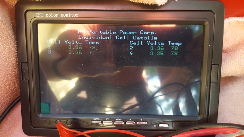
Finally had time to start playing with my 200aH LiFePO4 battery and solar setup. To start, the battery showed up nicely balanced.
It has been raining so I'm dragging the battery in and out of the garage via my daughter's wagon. She isn't thrilled and wants it back.
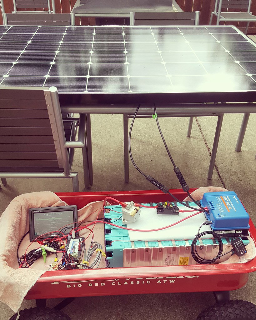
The spaghetti of wiring is mostly related to the LCD display monitor, so other than a disconnect switch between the solar panel and the charge controller, this is the basic mock-up. Also not shown is a low voltage contactor (operated by the BMS) and the inverter.
I found this chart for the 100 aH GBS cells. Mine are the newer 3rd generation 200aH cells but I assume the curve looks much the same:
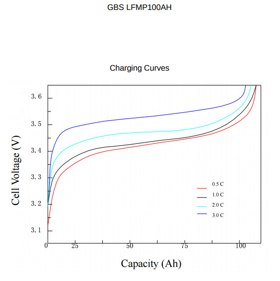
The red line, 0.5C, would assume charging at 50amps. I am mostly charging by solar and thus am closer to 0.05C. I am curious how that might look at this graph, as I have no idea what SOC I'm at at. At 3.36vpc (13.44v pack) charging at such a low rate I'm guessing I'm somewhere in the 28% SOC.
The BMS, display monitor and 2 contactors are collectively pulling 0.8 amps to stay alive. Not sure I'm happy about that, but even if I were not running a BMS I would still want to implement normally-open safety contactors.
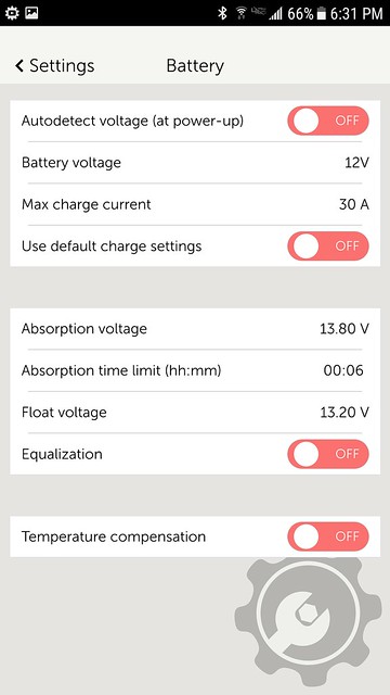
LETitROLL was absolutely right that Victron has updated the software for the charge controller and it now allows float time adjustable in 1 minute increments, where previously the minimum was 1 hour. I have the Victron solar charge controller set to BULK=13.8V, ABSORB 1 minute, FLOAT=13.3V. With those settings I will never hit the 3.55vpc required to active the cell balancers, which is precisely what I want--I will monitor for cell drift and manually balance if needed.
I am trying to work around an issue with my Magnum inverter/charger. When I plug into shorepower (120VAC) it goes straight to float. Then I read in the manual that "Charger says "Float Charging" not "Bulk Charging" when the AC is first plugged in: Check the DC Volts meter, if the battery is over 13.0 VDC then the battery was already charged, and the charger automatically goes to Float Charging to keep from overcharging the batteries." That doesn't help me if it won't start bulk charging until the battery dips to 12.9V, that is a very low SOC.Comment
-
Imbalance in the battery unless it is badly out of balance will only show up when the battery charge voltage is greater than around 3.4V
One thing I noticed with your setup is that you have the batteries on their side. It is bad to leave them on there side as the electrolyte moves to the side of the battery. They should be either preferably upright or on their back.
Here are some charge/discharge plots I did at the sort of charge rates that we work with.I found this chart for the 100 aH GBS cells. Mine are the newer 3rd generation 200aH cells but I assume the curve looks much the same:
The red line, 0.5C, would assume charging at 50amps. I am mostly charging by solar and thus am closer to 0.05C. I am curious how that might look at this graph, as I have no idea what SOC I'm at at. At 3.36vpc (13.44v pack) charging at such a low rate I'm guessing I'm somewhere in the 28% SOC.
ChargeDischargeCurves.jpg
Might be worth looking at solid state MOSFET switches or latching relays, you could also use a normally closed relay to disconnect the solar array from the controller if any cell voltages go too high. Latching relays will be more complex to interface.The BMS, display monitor and 2 contactors are collectively pulling 0.8 amps to stay alive. Not sure I'm happy about that, but even if I were not running a BMS I would still want to implement normally-open safety contactors.
I charge to 3.45V/cell (13.8V) until the charge current drops to C/50 then drop to a float voltage of 3.35V/cell (13.4V). As you have the balancing circuitry in the BMS you could monitor the imbalance and when it gets too bad raise the charge voltage to 3.55V/cell (14.2V) for a few hours and let your BMS do the balance for you.I have the Victron solar charge controller set to BULK=13.8V, ABSORB 1 minute, FLOAT=13.3V. With those settings I will never hit the 3.55vpc required to active the cell balancers, which is precisely what I want--I will monitor for cell drift and manually balance if needed.
Although it is going straight to float it might still put out full current until the battery voltage reaches the float voltage?I am trying to work around an issue with my Magnum inverter/charger. When I plug into shorepower (120VAC) it goes straight to float. Then I read in the manual that "Charger says "Float Charging" not "Bulk Charging" when the AC is first plugged in: Check the DC Volts meter, if the battery is over 13.0 VDC then the battery was already charged, and the charger automatically goes to Float Charging to keep from overcharging the batteries." That doesn't help me if it won't start bulk charging until the battery dips to 12.9V, that is a very low SOC.
Simon
Off grid 24V system, 6x190W Solar Panels, 32x90ah Winston LiFeYPO4 batteries installed April 2013
BMS - Homemade Battery logger github.com/simat/BatteryMonitor
Latronics 4kW Inverter, homemade MPPT controller
Off-Grid LFP(LiFePO4) system since April 2013Comment
-
That is something I never thought about; particularly since GBS packages these cells, stores and ships them on their side. How critical is this, as it would be very difficult for me to mount this in any position other than on its side.
Very interesting chart, thank you for posting that. I wonder how similar my GBS cells would be compared to the Winstons. If you look at the chart I posted, 3.35vpc would be about 28% SOC at 0.5C while a .05C charge on your chart could be 65% SOC. Goes to show why you can't rely on voltage with LiFePO4 cells, which makes it a little more nerve wracking for newbies like me.Here are some charge/discharge plots I did at the sort of charge rates that we work with.
ChargeDischargeCurves.jpg
These are the only settings I can adjust in my solar charge controller. Do you see any problems with these settings?I charge to 3.45V/cell (13.8V) until the charge current drops to C/50 then drop to a float voltage of 3.35V/cell (13.4V). As you have the balancing circuitry in the BMS you could monitor the imbalance and when it gets too bad raise the charge voltage to 3.55V/cell (14.2V) for a few hours and let your BMS do the balance for you.
Regarding the inverter/charger:
The charger was only matching the 0.8 amps being pulled by the BMS, contractors & LCD screen, according to the shunt-based reading and I confirmed with a clamp meter.Although it is going straight to float it might still put out full current until the battery voltage reaches the float voltage?
Comment

Comment