Does my MPPT SCC and 120V charger choice make sense for my LiFeMnPO4 batteries?

Collapse
X
 
  • Time
  • Show
Clear All
new posts
  • karrak
    Junior Member
    • May 2015
    • 528

    #76
    Originally posted by ASprinter
    What you may not realize is this battery "kit" includes a 7" LCD monitor that tells me individual cell voltages and temperatures, pack-level voltage, amps in/out of the battery and calculated SOC in percent. The latter feature does not become active until you do one full charge. That's what I was doing. All features on the LCD now work as they should.
    One thing to bear in mind is that the BMS calculates the SOC by subtracting the number of amps going out of the battery per unit of time from the number of amps going into the battery per unit of time and converting this to a percentage. The Elite manual says that the SOC is reset when the the battery voltage 3.52 x the number of cells in the battery. In your case this would be 14.08V. If the battery had a coulomb/current efficiency of 100% you would only have to reset the SOC once, unfortunately this is not the case and some current gets lost within the battery. Because of this you will have to reset the SOC reading on a regular basis for the reading that is shown to be accurate. If Elite don't make any compensation for the current being lost you should reset the SOC counter every few days.

    Simon

    Off grid 24V system, 6x190W Solar Panels, 32x90ah Winston LiFeYPO4 batteries installed April 2013
    BMS - Homemade Battery logger github.com/simat/BatteryMonitor
    Latronics 4kW Inverter, homemade MPPT controller

    Off-Grid LFP(LiFePO4) system since April 2013

    Comment

    • karrak
      Junior Member
      • May 2015
      • 528

      #77
      Originally posted by ASprinter
      On paper, 3.55vpc is "full," and is the point at which the vampire boards turn on. According to the chart, 3.4vpc, which equals the nominal battery voltage of 13.6v you are suggesting, is also very close to a full battery.

      Can you explain why floating at 13.6v wouldn't leave me with a battery around 99% full? The answer is probably that I am discharging at way less than 0.5C and I have no idea how to extrapolate how that might look on the graph I posted. Thanks for humoring me with this.
      You are correct, floating the battery at 13.6v and letting the charge current going into the battery taper off to zero will leave your battery very close to 99% full. With your 300W panel your maximum charge current is going to be ~22A or around 0.2C. Even at your maximum charge current your battery is going to be around 90% full when the voltage climbs through 13.6V.

      Simon

      Off grid 24V system, 6x190W Solar Panels, 32x90ah Winston LiFeYPO4 batteries installed April 2013
      BMS - Homemade Battery logger github.com/simat/BatteryMonitor
      Latronics 4kW Inverter, homemade MPPT controller
      Off-Grid LFP(LiFePO4) system since April 2013

      Comment

      • karrak
        Junior Member
        • May 2015
        • 528

        #78
        Originally posted by ASprinter
        I feel like I have a good handle on the solar, so now turning to my Magnum inverter/charger shore power source. If I use the "custom battery" setting it lets me set 13.8v absorb, float and equalize (eq can't be less than absorb) but absorb time is a min of 1 hr. I am guessing that absorb will be trying to push some level of amperage into the battery for an hour and that seems like a bad idea. There is a CC/CV mode that lets me set the voltage and has three options for terminating, Done Time, Done Amps or Hold VDC. Done Time is problematic because the minimum is 1 hr. Done Amps is problematic for two reasons, one is it seems I want to terminate charging before there is charge taper and second, Magnum doesn't recommend using this setting without their BMK (battery monitoring kit), i.e. the measurement via shunt. I looked into it and the shunt that came with my BMS is a 500A 50mV shunt and the Magnum shunt shares the same specs. A quick read on the internet makes it sound like I can have both my BMS and the Magnum BMK (which I did not buy) hooked to the same shunt. The third option, hold VDC, I'm guessing I wouldn't want to use with a LiFePO4.

        Adding to the confusion the manual says that in the Done Amps setting you can set the Done Amps to 0 and that will keep the charger in CV charge mode until the Max Time setting is reached, and that is adjustable from 0.1 minute up. If it works the way I think it does, that might be the ticket.
        How you set up the "shore charger" is going to be dependent on how you are going to be using it. If it is only going to be a backup when there is not enough solar power I would think you would only want to set it up to charge the battery up to around 40%-50% and let the solar do the rest. Is this how you will be using it?

        Simon

        Off grid 24V system, 6x190W Solar Panels, 32x90ah Winston LiFeYPO4 batteries installed April 2013
        BMS - Homemade Battery logger github.com/simat/BatteryMonitor
        Latronics 4kW Inverter, homemade MPPT controller
        Off-Grid LFP(LiFePO4) system since April 2013

        Comment

        • karrak
          Junior Member
          • May 2015
          • 528

          #79
          Originally posted by Sunking
          First thing you have to understand is Floating; the battery is neither charging or discharging. There is no current. The battery is not charging or discharging.

          In a working Off-Grid Battery Solar System, you are always charging if the sun is up, or discharging when the sun is up or dark. It never sits Floating in the technical sense. With your BMS, you always have a load draining your batteries. You will never Float in the technical sense. You are letting terms trip you up.
          In an off-Grid system you are not always charging when the sun is up. When you are talking about charging the object is the battery and the verb is charging, you said so in your first paragraph. The other circuitry connected to the battery is being powered by the solar panels, it is not being charged by the solar panels. The BMS is not always draining the battery. When the battery is floating the BMS is being powered from the solar panels and there is little if any current coming or going into each of the cells in the battery. So yes, technically you are floating the battery when the charge going into the individual cells in the battery gets close to zero.

          Pick any point on that graph. For example the 50 AH discharge point (50% SOC) and look at the voltages. Dead center between the knees.

          If OCV were printed would read 3.3 volts. (I will explain how I know that in a moment)
          At .5c reads 3.25 volts
          At 1C reads 3.2volts
          At 2C reads 3.1 volts
          At 3C reads 3.0 volts.

          I know OCV voltage = 3.3 volts because from the graph I can calculate the battery Internal Resistance aka Ri = .001 Ohms which is what your batteries should be new. So here is the math and numbers.
          This is just not true, Here is the graph with some guide lines on it to make it easier to see the actual readings.
          GBSGuideLines.jpg
          From the graph you can see that
          0.5C is at ~3.21V
          1.0C is at ~3.20V
          2.0C is at ~3.15V
          3.0C is at ~3.01V
          This completely throws your calculations out and shows that internal battery resistance is not constant and dependent on charge current, could it be something to do with charge transport?

          So apply your Boat Forum Logic. How is 3.3 volts 99% when on your batteries are 50% @ 3.3 OCV. 3.3 means nothing unless it is OCV. Depending on if you are charging, discharging or Floating. At 50% SOC can be anywhere from 3.0 to 3.6 volts. That is anywhere from dead to fully charged by Boat Forum and Karrak logic.
          I think you will find The Cruiser forum is talking about a float voltage of 3.3V which equates to an SOC of around 70%.

          Simon

          Off grid 24V system, 6x190W Solar Panels, 32x90ah Winston LiFeYPO4 batteries installed April 2013
          BMS - Homemade Battery logger github.com/simat/BatteryMonitor
          Latronics 4kW Inverter, homemade MPPT controller
          Off-Grid LFP(LiFePO4) system since April 2013

          Comment

          • ASprinter
            Junior Member
            • Mar 2017
            • 39

            #80
            Originally posted by karrak
            How you set up the "shore charger" is going to be dependent on how you are going to be using it. If it is only going to be a backup when there is not enough solar power I would think you would only want to set it up to charge the battery up to around 40%-50% and let the solar do the rest. Is this how you will be using it?
            That is one scenario. Generally solar will be my main source of charging probably 95%+ of the time but I see using shorepower if the solar is unable to keep up. There will also be a 600 watt inverter that will provide 120VAC shorepower to the Magnum inverter/charger that I will be able to turn on with a switch when the engine is running. I know it's inefficient to take 14v alternator power, turn it into 120v then back to 12v at the charger, but it's awfully convenient from a packaging and cost perspective, but more than anything it prevents having to run large gauge DC wire on a long run back to the inverter.

            Regarding the BMS coulomb counting, if both my BMS and the Magnum can share the same 50mV shunt, I might go ahead and buy the Magnum BMK (the kit without the actual shunt) just to have that amps in/out tracking on the Magnum remote screen. Amps in/out is something my BMS does not report, just a calculated battery SOC.

            Comment

            • Sunking
              Solar Fanatic
              • Feb 2010
              • 23301

              #81
              Originally posted by karrak
              This completely throws your calculations out and shows that internal battery resistance is not constant and dependent on charge current, could it be something to do with charge transport?
              Karrak Ri remains fairly constant in a lithium battery. It does not change with the amount of current directly. The deviance you are nit picking is higher currant causes higher temps which lower Ri. If you look for graphs of LFP battery Ri, the Ri looks fairly flap oveer the useful SOC range. It goes up slightly as SOC goes up, and goes down and SOC goes down. It falls off the cliff when completely discharged and shorts out which is death of a lithium battery. Lithium batteries like everything on earth and the heavens live by Ohm;s Law. Only in Karrak's twisted mind does that ever change. No matter what you say, you cannot change math or Ohm's Law. It is the law of physics, not a Speed Limit or No Smoking Sign that can be ignored.
              Last edited by Sunking; 06-20-2017, 08:06 PM.
              MSEE, PE

              Comment

              • Sunking
                Solar Fanatic
                • Feb 2010
                • 23301

                #82
                Originally posted by ASprinter
                The math did it for me, that makes perfect sense and I really appreciate you taking the time to explain. That actually ties this whole thread together and explains some of the concepts I was missing.
                Great, you now know more and understand better than Karrak.

                Originally posted by ASprinter
                I feel like I have a good handle on the solar, so now turning to my Magnum inverter/charger shore power source. If I use the "custom battery" setting it lets me set 13.8v absorb, float and equalize (eq can't be less than absorb) but absorb time is a min of 1 hr. I am guessing that absorb will be trying to push some level of amperage into the battery for an hour and that seems like a bad idea. There is a CC/CV mode that lets me set the voltage and has three options for terminating, Done Time, Done Amps or Hold VDC.
                Forget EQ, disable it. You want HOLD DC. Go back to the math and it will help you understand. Solve this equation of a charging battery How many amps are flowing?

                Charge Amps = [Charge Voltage - Battery OCV] / Ri

                Where

                Charger Voltage = 13.6 volts
                Battery OCV = 13.6 volts.
                Ri = Some Integer greater than 0, and less than infinity Ohms, called x

                [13.6 - 13.6] / Some number greater than 0 = 0 / x = 0 Amps

                See what is happening? For there to be any charge current there must be a difference between the charger voltage and battery OCV. 0 volts / by any number = 0 Amps on earth and heaven. Only in Karrrak' s world can there be current with no voltage potential difference. When Battery OCV and Charge Voltage are equal, the battery is Floating and/or Saturated and no current is flowing.

                What you are looking for is that magic voltage between 13.4 and 13.6 volts that gives you th eSOC you want less than 100%. If your panel wattage is right. somewhere around mid day, your battery will Float. Assuming the power demand is lower or equal to what the panels can produce, power to the loads will come from the panels. Otherwise the battery will make up for the shortage. This saves your battery power for night. Understand?

                I am not familiar with your charger, but I do know how to fool it and make it do what you want. Think outside the box. Example set Bulk/Absorb to 13.4 volts and float to 13.6 volts. Or Set Bulk = Absorb = Float = 13.6 volts.

                Now i will say this again. Don't get hung up on 13.6 volts. It is not set in stone. Experiment to find the right voltage that correlates to the SOC you want. Lastly remember this my friend. I learned this first day in college from my engineering instructor and still my fiend and golf partner today. In engineering design:

                We measure things with a Micrometer.
                We mark the spot with Chalk.

                We cut it with an Axe.


                Don't sweat the details. Make the adjustments as you go to make it work.


                Last edited by Sunking; 06-20-2017, 08:39 PM.
                MSEE, PE

                Comment

                • karrak
                  Junior Member
                  • May 2015
                  • 528

                  #83
                  Originally posted by ASprinter
                  Regarding the BMS coulomb counting, if both my BMS and the Magnum can share the same 50mV shunt, I might go ahead and buy the Magnum BMK (the kit without the actual shunt) just to have that amps in/out tracking on the Magnum remote screen. Amps in/out is something my BMS does not report, just a calculated battery SOC.
                  Before you buy the BMK I would make sure that it will reset itself properly with your solar charging scheme. The manual says:
                  The battery's state of charge which is the best indicator of the condition of the batteries is indicated on your remote/router's SOC display. This display shows that the batteries are fully charged (i.e., SOC = 100%) once the following three conditions have been met: 1. The charging voltage stabilizes over time (see Figure 3-1). 2. The charging current decreases to a low percentage of the AH capacity normally less than 2%. 3. The AH removed from the battery are within 1% of fully being returned.
                  This looks like it is designed to detect a lead acid battery going into float after it has been fully charged.

                  I would contact Magnum and tell them what battery you have and your solar charge regime and see if they think the BMK will work for you and/or make sure you can return the unit if it doesn't work.

                  Simon
                  Off grid 24V system, 6x190W Solar Panels, 32x90ah Winston LiFeYPO4 batteries installed April 2013
                  BMS - Homemade Battery logger github.com/simat/BatteryMonitor Latronics 4kW
                  Inverter, homemade MPPT controller
                  Off-Grid LFP(LiFePO4) system since April 2013

                  Comment

                  • karrak
                    Junior Member
                    • May 2015
                    • 528

                    #84
                    Originally posted by Sunking
                    Karrak Ri remains fairly constant in a lithium battery. It does not change with the amount of current directly. The deviance you are nit picking is higher currant causes higher temps which lower Ri. If you look for graphs of LFP battery Ri, the Ri looks fairly flap oveer the useful SOC range. It goes up slightly as SOC goes up, and goes down and SOC goes down. It falls off the cliff when completely discharged and shorts out which is death of a lithium battery. Lithium batteries like everything on earth and the heavens live by Ohm;s Law. Only in Karrak's twisted mind does that ever change. No matter what you say, you cannot change math or Ohm's Law. It is the law of physics, not a Speed Limit or No Smoking Sign that can be ignored.
                    Using your Ri formula and a Voc of 3.3V I get the following Ri values for the various charge rates
                    0.5C Ri=1.8mOhms
                    1.0C Ri=1.0mOhms
                    2.0C Ri=0.75mOhms
                    3.0C Ri=0.96mOhms
                    If your heat theory was right i don't think we would get these figures.

                    You are right when you say that the battery has to obey the laws of physics and Ohms law. The process of converting the chemical energy stored in the battery into the electrical energy that goes into the external electrical circuit is a chemical process that has to obey the laws of chemistry. The chemical processes have an impact on what we see as internal battery resistance. You are right that the Ri of a battery would not vary much if there were no chemical processes going on in the battery but this is obviously not the case.

                    You say "Don't sweat the details. Make the adjustments as you go to make it work." , I say "the devil is in the detail" and "attention to detail". I would rather get the details right from the start rather than have unpleasant surprises happening later on...

                    Simon
                    Off grid 24V system, 6x190W Solar Panels, 32x90ah Winston LiFeYPO4 batteries installed April 2013
                    BMS - Homemade Battery logger github.com/simat/BatteryMonitor Latronics 4kW
                    Inverter, homemade MPPT controller
                    Off-Grid LFP(LiFePO4) system since April 2013

                    Comment

                    • Sunking
                      Solar Fanatic
                      • Feb 2010
                      • 23301

                      #85
                      Originally posted by karrak

                      Using your Ri formula and a Voc of 3.3V I get the following Ri values for the various charge rates
                      0.5C Ri=1.8mOhms
                      1.0C Ri=1.0mOhms
                      2.0C Ri=0.75mOhms
                      3.0C Ri=0.96mOhms
                      If your heat theory was right i don't think we would get these figures.

                      You are right when you say that the battery has to obey the laws of physics and Ohms law. The process of converting the chemical energy stored in the battery into the electrical energy that goes into the external electrical circuit is a chemical process that has to obey the laws of chemistry. The chemical processes have an impact on what we see as internal battery resistance. You are right that the Ri of a battery would not vary much if there were no chemical processes going on in the battery but this is obviously not the case.
                      You are in denial of facts.

                      MSEE, PE

                      Comment

                      • ASprinter
                        Junior Member
                        • Mar 2017
                        • 39

                        #86
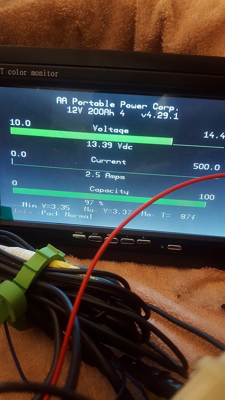
                        Just completed my battery's second charge cycle, but this was the first time I used the Magnum inverter/charger to do the charging . I had the Magnum set for cc/cv at 13.5v thinking I would end at a conservatively low SOC, but I manually terminated the charge early at 13.44v as I did not desire a 100% full battery. What I didn't expect was how soon the Magnum inverter/charger would start reducing current down to just a few amps (more on that in a second.) At a 2.7A charge rate, pack voltage was at 13.44V and SOC was stated at 97%. I had added a 2.5A load when the picture was taken.


                        As stated in an earlier post, the moment the Magnum inverter/charger detects shorepower (120vac) it checks the battery voltage and if that voltage is over 13.0V it skips bulk/absorb and goes straight to float "to not overcharge the battery" (lead acid thinking). Obviously 13.0V is a low SOC on my battery, so it started in float and floated at 18A until battery voltage was around 13.37 then started reducing amperage. By 13.39 volts it was only sending about 6 amps to the battery. By 13.44v it was down to 2.7A. The low-C float was going to fill the battery with only a 13.5V float setting.

                        This inverter/charger has more settings than most, but it's not the right equipment for the job, mainly due to that 13.0V forced-float-at-startup thing. Luckily I won't be using this to charge much, so the work-around is probably to set a super low float of 13.3. It also means I loose out on the ability to do a quick battery recharge due to the missing bulk phase. I'll continue to experiment.

                        Comment

                        • Sunking
                          Solar Fanatic
                          • Feb 2010
                          • 23301

                          #87
                          Lower the voltage.

                          But warning here, just how are you determining SOC. Voltage means nothing. So f your equipment is using voltage, it is a big fat lie.

                          The only way to really know SOC is to fully charge each cell to 3.6 volts until current tapers to 2 to 4 amps. Rest it, then fully discharge it and measure AH of each cell. Say a cell measures 100 AH. Now you recharge and only put in 93 AH to get to 90% SOC. Your batteries are roughly 97% efficient charging meaning it will take 103 AH in to have 100 AH capacity.

                          You can use a Coulomb counter, but even that is flawed because of battery charge efficiency. They have to be recalibrated every cycle or two to be useful.

                          Life is much simpler if you just Bottom Balance and charge to 13.4 to 13.6 volts and quit worrying about minor meaningless details. As long as you are not taking your cells above 3.45 volts, no stress. That is why A123 Systems recommends float charging LFP cells to 3,45 vpc for extended battery life accepting less than fully charged. Try to remember the 3 Golden Rules of design.

                          1. Measure things with a Micrometer.
                          2. Mark the spot with Chalk.
                          3. Cut it with an Axe.

                          Well there is a 4th rule and best of all. KISS (keep it simple stupid)
                          Last edited by Sunking; 06-21-2017, 05:35 PM.
                          MSEE, PE

                          Comment

                          • ASprinter
                            Junior Member
                            • Mar 2017
                            • 39

                            #88
                            Yes, I am not stressing at all, the lowest cell was at 3.35v and highest at 3.37v. I'm not sure how the BMS and shunt interact for the SOC display and don't care, the more I use it I will learn whether or not they mean anything at all. I am thinking I would like something that tracks amp hours in and out (like perhaps a Victron BVM702 or similar) so I have a better idea whether or not the energy I am gaining from solar is offsetting what I use. Maybe the addition of the Magnum BMK would give me the same functionality, but the fact that I don't do a full charge might not make those very effective either.

                            This exercise helped prove to me just how irrelevant voltage is when determining SOC. A high charge rate over a short period of time will produce a much different result than a low charge rate over a long span of time, meaning one setting for my various chargers is not practical. I'll just have to play with each and see where I end up.

                            I used your mic/chalk/axe anology in a staff meeting yesterday, love it.

                            Comment

                            • karrak
                              Junior Member
                              • May 2015
                              • 528

                              #89
                              You are finding out that it is very hard to charge an LFP battery to an SOC that is not in the high 90% region with low charge rates in a reasonable time, especially if the charge current is not constant.

                              I can understand your reluctance to charge your battery to >95%SOC. When I first set my off grid system up with an LFP battery the accepted wisdom seemed to be not to charge above 90% and to not float the battery. My first charge settings were to charge to 3.375V/cell and terminate the charge and not start a new charge till the next day. This regime meant that my battery might be anywhere between ~75%-~95% at the end of the day even if there had been enough solar power to fully charge my battery. This is not very helpful if you don't know if there will be enough sun in the next few days and do not want to use a generator.

                              After some research and seeing that there were a number of people in Australia who have been charging and floating their battery at around 98% when the sun was up with no noticeable degradation of their batteries I decided to switch to this charge regime about three years ago. In April this year which is the fourth anniversary of my LFP battery being installed and after around 1,500 cycles the SOC went down to the lowest value that I have ever recorded of ~8%. The average cell voltage at this SOC was 3.0375V which I calculate to be a real SOC of around 5%.

                              But what about Maine Sails tests on the cruiser forum which is backed up by this graph?
                              LiIonstorage.jpg
                              If you look at the LFP cells graphs you can see that the cells they used lost ~5.5% of there capacity when stored at ~70%-100% at 25C for nine moths, ~3% at SOC between ~40%-70% then tapering down to no loss at 0%.

                              The big difference between my off grid system and others like my system and these cells is that my cells are in use all the time whereas the cells being tested are not.

                              The lesson here is that if you are just storing the cells discharge them down to as low an SOC as you are comfortable with bearing in mind that the cells will self discharge or float them at a voltage of around 3.0V. On the other hand if you are using the battery all the time and are reliant on an unreliable power source like solar charge them up >95% and float them at whatever you are comfortable with to get the best possible use out of the battery.

                              Simon
                              Off grid 24V system, 6x190W Solar Panels, 32x90ah Winston LiFeYPO4 batteries installed April 2013
                              BMS - Homemade Battery logger github.com/simat/BatteryMonitor Latronics 4kW
                              Inverter, homemade MPPT controller
                              Off-Grid LFP(LiFePO4) system since April 2013

                              Comment

                              • karrak
                                Junior Member
                                • May 2015
                                • 528

                                #90
                                Originally posted by Sunking
                                The only way to really know SOC is to fully charge each cell to 3.6 volts until current tapers to 2 to 4 amps. Rest it, then fully discharge it and measure AH of each cell. Say a cell measures 100 AH. Now you recharge and only put in 93 AH to get to 90% SOC. Your batteries are roughly 97% efficient charging meaning it will take 103 AH in to have 100 AH capacity.
                                You can also charge them to 3.45V until the current tapers to C/50 (in the OP's case ~2A) and call this 99%. This is what I do, although I call it 100%. If you use the stated capacity of the cells rather than discharging them to calculate the 0%SOC you will not be far out with new cells. The coulomb/current efficiency of LFP batteries is not 97%, it is around 99.5%.

                                You can use a Coulomb counter, but even that is flawed because of battery charge efficiency. They have to be recalibrated every cycle or two to be useful.
                                If you can input the efficiency of the battery into the coulomb counter it could remain accurate for up to a week or even better if it learns what the efficiency is it could go several weeks or tens of cycles without getting too inaccurate.

                                Life is much simpler if you just Bottom Balance and charge to 13.4 to 13.6 volts and quit worrying about minor meaningless details. As long as you are not taking your cells above 3.45 volts, no stress. That is why A123 Systems recommends float charging LFP cells to 3,45 vpc for extended battery life accepting less than fully charged.
                                Even simpler I would have thought because it doesn't need a bottom balance and might make the battery last longer and will charge the battery up as quickly as possible is for the OP to:
                                • When out camping and the battery is in use set the Victron to bulk charge at 13.8V-13.7V with an absorb time of 0-15 minutes and drop to a float voltage of 3.35V-3.30V depending on what SOC you want to float the battery at.
                                • When the unit is sitting at home not being used set the Victron (if it will let you) to a bulk and float voltage of 12.8V. This of course assumes that the solar panel remains out in the sun.
                                • A couple of days before you use the battery again set the Victron back to the in-use settings to recharge the battery.
                                • If you notice that the individual cell voltages are diverging when the charge voltage is at 13.8V do a balance by doing a charge at 14.2V with a longer absorb time to give the balancing boards time to balance the battery.
                                • If there is not enough sunshine to match your usage, wait till the battery has discharged to ~20% (which will be less than 13V) and use the magnum to charge the battery up to 40%-50% either by timing the charge or setting a low charge voltage on the Magnum.

                                Simon
                                Off grid 24V system, 6x190W Solar Panels, 32x90ah Winston LiFeYPO4 batteries installed April 2013
                                BMS - Homemade Battery logger github.com/simat/BatteryMonitor Latronics 4kW
                                Inverter, homemade MPPT controller
                                Off-Grid LFP(LiFePO4) system since April 2013

                                Comment

                                Working...