
That is one scenario. Generally solar will be my main source of charging probably 95%+ of the time but I see using shorepower if the solar is unable to keep up. There will also be a 600 watt inverter that will provide 120VAC shorepower to the Magnum inverter/charger that I will be able to turn on with a switch when the engine is running. I know it's inefficient to take 14v alternator power, turn it into 120v then back to 12v at the charger, but it's awfully convenient from a packaging and cost perspective, but more than anything it prevents having to run large gauge DC wire on a long run back to the inverter.
Regarding the BMS coulomb counting, if both my BMS and the Magnum can share the same 50mV shunt, I might go ahead and buy the Magnum BMK (the kit without the actual shunt) just to have that amps in/out tracking on the Magnum remote screen. Amps in/out is something my BMS does not report, just a calculated battery SOC.
-
In an off-Grid system you are not always charging when the sun is up. When you are talking about charging the object is the battery and the verb is charging, you said so in your first paragraph. The other circuitry connected to the battery is being powered by the solar panels, it is not being charged by the solar panels. The BMS is not always draining the battery. When the battery is floating the BMS is being powered from the solar panels and there is little if any current coming or going into each of the cells in the battery. So yes, technically you are floating the battery when the charge going into the individual cells in the battery gets close to zero.
This is just not true, Here is the graph with some guide lines on it to make it easier to see the actual readings.Pick any point on that graph. For example the 50 AH discharge point (50% SOC) and look at the voltages. Dead center between the knees.
If OCV were printed would read 3.3 volts. (I will explain how I know that in a moment)
At .5c reads 3.25 volts
At 1C reads 3.2volts
At 2C reads 3.1 volts
At 3C reads 3.0 volts.
I know OCV voltage = 3.3 volts because from the graph I can calculate the battery Internal Resistance aka Ri = .001 Ohms which is what your batteries should be new. So here is the math and numbers.
GBSGuideLines.jpg
From the graph you can see that
0.5C is at ~3.21V
1.0C is at ~3.20V
2.0C is at ~3.15V
3.0C is at ~3.01V
This completely throws your calculations out and shows that internal battery resistance is not constant and dependent on charge current, could it be something to do with charge transport?
I think you will find The Cruiser forum is talking about a float voltage of 3.3V which equates to an SOC of around 70%.So apply your Boat Forum Logic. How is 3.3 volts 99% when on your batteries are 50% @ 3.3 OCV. 3.3 means nothing unless it is OCV. Depending on if you are charging, discharging or Floating. At 50% SOC can be anywhere from 3.0 to 3.6 volts. That is anywhere from dead to fully charged by Boat Forum and Karrak logic.
Simon
Off grid 24V system, 6x190W Solar Panels, 32x90ah Winston LiFeYPO4 batteries installed April 2013
BMS - Homemade Battery logger github.com/simat/BatteryMonitor
Latronics 4kW Inverter, homemade MPPT controllerLeave a comment:
-
How you set up the "shore charger" is going to be dependent on how you are going to be using it. If it is only going to be a backup when there is not enough solar power I would think you would only want to set it up to charge the battery up to around 40%-50% and let the solar do the rest. Is this how you will be using it?
Simon
Off grid 24V system, 6x190W Solar Panels, 32x90ah Winston LiFeYPO4 batteries installed April 2013
BMS - Homemade Battery logger github.com/simat/BatteryMonitor
Latronics 4kW Inverter, homemade MPPT controller
Leave a comment:
-
You are correct, floating the battery at 13.6v and letting the charge current going into the battery taper off to zero will leave your battery very close to 99% full. With your 300W panel your maximum charge current is going to be ~22A or around 0.2C. Even at your maximum charge current your battery is going to be around 90% full when the voltage climbs through 13.6V.
Simon
Off grid 24V system, 6x190W Solar Panels, 32x90ah Winston LiFeYPO4 batteries installed April 2013
BMS - Homemade Battery logger github.com/simat/BatteryMonitor
Latronics 4kW Inverter, homemade MPPT controllerLeave a comment:
-
One thing to bear in mind is that the BMS calculates the SOC by subtracting the number of amps going out of the battery per unit of time from the number of amps going into the battery per unit of time and converting this to a percentage. The Elite manual says that the SOC is reset when the the battery voltage 3.52 x the number of cells in the battery. In your case this would be 14.08V. If the battery had a coulomb/current efficiency of 100% you would only have to reset the SOC once, unfortunately this is not the case and some current gets lost within the battery. Because of this you will have to reset the SOC reading on a regular basis for the reading that is shown to be accurate. If Elite don't make any compensation for the current being lost you should reset the SOC counter every few days.
Simon
Off grid 24V system, 6x190W Solar Panels, 32x90ah Winston LiFeYPO4 batteries installed April 2013
BMS - Homemade Battery logger github.com/simat/BatteryMonitor
Latronics 4kW Inverter, homemade MPPT controller
Leave a comment:
-
The math did it for me, that makes perfect sense and I really appreciate you taking the time to explain. That actually ties this whole thread together and explains some of the concepts I was missing.
I feel like I have a good handle on the solar, so now turning to my Magnum inverter/charger shore power source. If I use the "custom battery" setting it lets me set 13.8v absorb, float and equalize (eq can't be less than absorb) but absorb time is a min of 1 hr. I am guessing that absorb will be trying to push some level of amperage into the battery for an hour and that seems like a bad idea. There is a CC/CV mode that lets me set the voltage and has three options for terminating, Done Time, Done Amps or Hold VDC. Done Time is problematic because the minimum is 1 hr. Done Amps is problematic for two reasons, one is it seems I want to terminate charging before there is charge taper and second, Magnum doesn't recommend using this setting without their BMK (battery monitoring kit), i.e. the measurement via shunt. I looked into it and the shunt that came with my BMS is a 500A 50mV shunt and the Magnum shunt shares the same specs. A quick read on the internet makes it sound like I can have both my BMS and the Magnum BMK (which I did not buy) hooked to the same shunt. The third option, hold VDC, I'm guessing I wouldn't want to use with a LiFePO4.
Adding to the confusion the manual says that in the Done Amps setting you can set the Done Amps to 0 and that will keep the charger in CV charge mode until the Max Time setting is reached, and that is adjustable from 0.1 minute up. If it works the way I think it does, that might be the ticket.
I don't expect anyone to know the ins and outs of my inverter/charger, I'm probably just talking out loud here, but these options are discussed on Page 21 if anyone does happen to be interested. http://www.magnum-dimensions.com/sit...-ME-RC_Web.pdfLeave a comment:
-
First thing you have to understand is Floating; the battery is neither charging or discharging. There is no current. The battery is not charging or discharging.
In a working Off-Grid Battery Solar System, you are always charging if the sun is up, or discharging when the sun is up or dark. It never sits Floating in the technical sense. With your BMS, you always have a load draining your batteries. You will never Float in the technical sense. You are letting terms trip you up.
One thing you have not wrapped your noodle around is the difference between a battery that is Open Circuit Voltage (aka Floating on a charger), Charging and Discharging. All three are different voltages. You can have a fully charged cell that measures 3.6 volts when charging, 3.45 volts when OCV, and 3.0 volts when discharging. Look at your own graph and move away from the knees. Wished they showed OCV voltage because it is easier to see what I am talking about. Pick any point on that graph. For example the 50 AH discharge point (50% SOC) and look at the voltages. Dead center between the knees.
If OCV were printed would read 3.3 volts. (I will explain how I know that in a moment)
At .5c reads 3.25 volts
At 1C reads 3.2volts
At 2C reads 3.1 volts
At 3C reads 3.0 volts.
I know OCV voltage = 3.3 volts because from the graph I can calculate the battery Internal Resistance aka Ri = .001 Ohms which is what your batteries should be new. So here is the math and numbers.
.5C = 50 amps
1C = 100 amps
2C = 200 amps
3C = 300 amps.
Ri = .001 Ohms.
The Voltage of a Discharging Battery = OCV - [Current x Ri]. We can also say the OCV = Battery Voltage under Discharge + [Current x Ri] Simple high school algebra.
Now we can prove it anyway you want to spin it. I said the OCV is 3.3 volts or 50% SOC. Lets see if the math works.
Does 3.3 volts = 3.25 volts + [50 amps x .001 Ohms]? 0.5C curve
Does 3.3 volts = 3.2 volts + [100 amps x .001 Ohms] ? 1C curve
Does 3.3 volts = 3.1 volts + [200 amps x .001 Ohms]? 2Cc curve
Does 3.3 volts = 3.0 volts + [300 amps x .001 Ohms]? 3C curve
The answer is hell YES. to all above and true statements. It is right there on your own graph. So 3.3 volts OCV voltage on your batteries is roughly 50% SOC +/- 20%. That is exactly what your own graph is telling you.
Now the the voltage of a Charging Battery = OCV + [Current x Ri]. Exact opposite of a discharging battery. Again simple high school algebra
Take your same graph at 50% SOC or OCV = 3.3 volts; What is the voltage when charging at .5C, 1C, 2C, and 3C? You had better say
3.35
3.4
3.4
3.6
So apply your Boat Forum Logic. How is 3.3 volts 99% when on your batteries are 50% @ 3.3 OCV. 3.3 means nothing unless it is OCV. Depending on if you are charging, discharging or Floating. At 50% SOC can be anywhere from 3.0 to 3.6 volts. That is anywhere from dead to fully charged by Boat Forum and Karrak logic.
FWIW 13.6 volts is not engraved in Stone. Experiment and find the exact voltage for your batteries via Discharge Test. Charge them to 13.6 volts, and discharge them to 2.6 volts and measure the AH. If that is say 95 AH, lower the voltage a little and repeat until you get what you want. There is no exact voltage. You have to find it. 13.6 is safe. You may find 13.45 is perfect. Figure it out. But get rid of that BMS, it is a Vampire.Last edited by Sunking; 06-19-2017, 08:17 PM.Leave a comment:
-
As we have discussed, the boating community thinks anything over a 13.3v float will overcharge the batteries. Can you help me explain how floating at 13.6v won't harm the battery? Here is the discharge curve for the GBS cells:
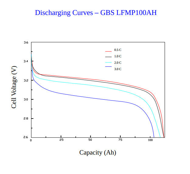
On paper, 3.55vpc is "full," and is the point at which the vampire boards turn on. According to the chart, 3.4vpc, which equals the nominal battery voltage of 13.6v you are suggesting, is also very close to a full battery.
Here are some screenshots from my BMS:
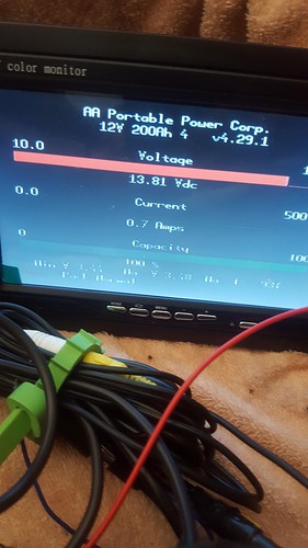
At 13.81V and at a 0.7A discharge rate the BMS is reporting a 100% full battery.
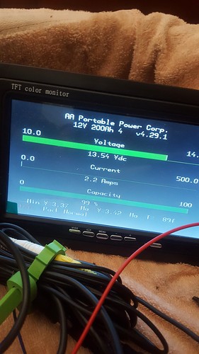
13.54V and 2.2A discharge reporting 99% full.
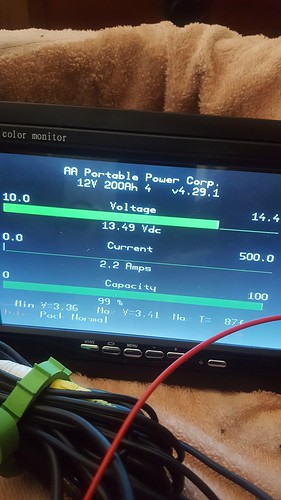
13.49v and 2.2A discharge reporting 99% full.

13.45v and 2.4A discharge reporting 98% full.
Can you explain why floating at 13.6v wouldn't leave me with a battery around 99% full? The answer is probably that I am discharging at way less than 0.5C and I have no idea how to extrapolate how that might look on the graph I posted. Thanks for humoring me with this.Leave a comment:
-
Set your Inverter LVD to 12 volts, Charge Controller to 13.6 volts and that is all you need once the batteries are balanced. Al that extra equipment you have will kill your batteries. Works for an EV, but not a solar system. You operate between 13,6 and 12 volts. Stay away from the knees at either end and your batteries will have maximum cycle life. Never let any cell go below 3 volts or above 3.5. If you Float at 13.6 volts, the batteries will saturate at 3.45 volts.
Head Mike's warning about Karrak. He is not welcome here and a fraud. The mods are itching to get rid of him permanently and using him as an example.
For a MPPT Controller use these formulas.
Output Current = Panel Wattage / Battery Voltage
Panel Power = Output Charge Current x Battery Voltage.
Be aware if you Top Balance like you are, you risk over discharging your batteries. Over discharge is instant death.Leave a comment:
-
Mike, Sunking, karrak, I am listening to all of you. You may have differing opinions but that is helping me learn. If my reply above seemed snarky I was just trying to point out that I charged to 100% one time because I had to, and I watched it like a hawk when I did it. I was not near disaster and I did not cause any damage to the batteries...one cell hit 3.61v for a few seconds, well within the operating parameters of this battery (3.8v is the cutoff). As soon as the BMS completed its full charge calibration I brought the batteries down to a much lower SOC. What you may not realize is this battery "kit" includes a 7" LCD monitor that tells me individual cell voltages and temperatures, pack-level voltage, amps in/out of the battery and calculated SOC in percent. The latter feature does not become active until you do one full charge. That's what I was doing. All features on the LCD now work as they should.
Thank you for explaining that. Helps explain the numbers I was seeing on my clamp meter.This is the magic of an MPPT controller, they work by "converting" voltage to current by the simple formula VSolar * ISolar = Vbattery * Ibattery. In your case Vsolar = 27.62V, Vbattery = 14.41V, Ibattery = 16.30A so the panel current is 8.50A (14.41*16.30/27.62). It would actually be slightly more than this at the charge controller is not 100% efficient.
That's the one. I'm looking into this today and will report back. I bought this particular inverter/charger because it does have more user flexibility than others I have seen.In the ME-ARC manual, is this the correct one? there is a whole section on setting up the CC/CV mode and setting up the different float modes. Your Inverter/Charger is very smart, impressive!Leave a comment:
-
As someone who is responsible for designing two off grid power systems with LFP batteries that have both been in operation for over four years with little if any change in perfomance and who has done allot of research and testing of LFP batteries, I think I can safely say
Bad things will start happening if you charge an LFP battery to 4.4v-4.5V/cell. Even with this abuse it is unlikely that they will catch fire.
It will not damage them by charging to 3.8V/cell but doing so will reduce their lifespan. It is not good to leave the cells at 3.8V for an extended period (days) of time
If you want fast charging 3.6V/cell is a suitable charging voltage but charging at high rates will reduce their lifespan. Again leaving them at 3.6V/cell for extended periods will reduce their lifespan.
When you say "soared from 3.55 to 3.61V" you are only talking about a 60mV increase in voltage and still well within the safe operating range of the battery. If the battery was balanced by the supplier and the charge voltage was set to 14.4V I would think that the higher cell might have got to ~3.7V and the others would have caught up to around 3.55-3.60V before the charge controller went into CV mode and started to limit the current. Because you have in my view wisely installed a BMS the worst that could have happened is that the highest cell would have got to 3.8V before the BMS disconnected the battery from the solar controller and no harm would have been done. It is better to use the overvoltage relay to disconnect the solar panel from the controller rather than the the controller from the battery as the controller relies on power from the battery to operate.
This is the magic of an MPPT controller, they work by "converting" voltage to current by the simple formula VSolar * ISolar = Vbattery * Ibattery. In your case Vsolar = 27.62V, Vbattery = 14.41V, Ibattery = 16.30A so the panel current is 8.50A (14.41*16.30/27.62). It would actually be slightly more than this at the charge controller is not 100% efficient.That's what the Victron solar charge controller software said, but I'm not sure how that could be. It stated 249 watts, 27.6 v and 16.3 amps, which equals 449 watts. My panel is only a 300w.
If you want to be very cautious you could increase the voltage by 0.1V per day until you reach 14.2V.Sounds like a good approach. I'll start low, 13.8v and 10 mins of float and see where I end up.
In the ME-ARC manual, is this the correct one? there is a whole section on setting up the CC/CV mode and setting up the different float modes. Your Inverter/Charger is very smart, impressive!That's what I thought too but the amperage coming from the inverter/charger is only matching the draw from the battery at the time; no charging. There is apparently a cc/cv mode that I have yet to find, so I am interested in researching that.
Simon
Off grid 24V system, 6x190W Solar Panels, 32x90ah Winston LiFeYPO4 batteries installed April 2013
BMS - Homemade Battery logger github.com/simat/BatteryMonitor
Latronics 4kW Inverter, homemade MPPT controller
Leave a comment:
-
Meh. words fail me. That's why I'm an engineer, not a salesman. Enjoy your batteries as long as last, and keep them away from flammable structures. Due Diligence done,
Nobody listens to an electronics engineer, when there's a good pitchman in the room. Sunking and I can go home now.Leave a comment:
-
-
Perhaps so, or is that a typo? I thought Bulk was CC and Absorb and Float were CV. No?
The BMS pulls 0.17 amps and the Tyco EV200 contractors (with the economizers) are around 0.2 amps each and there are two. The other 0.1 is from the LCD display. I have more solar and battery than I need and while I understand your sentiments about the vampire board's tendency to fail and kill a cell, I am new to this and the individual cell voltages and temperatures as well as the LV and HV cutouts seem like a worthy feature to have. I see them as training wheels. When I understand this a bit more perhaps I am willing to get rid of the protections.If your BMS pulls ,8 amps is going to be the destroyer of your batteries. That means you are burning 250 watt hours a day as waste heat for nothing. Elite BMS systems are notorious LFP battery killers. Get rid of it, you have no need for it.
I don't think you read my post very carefully. I had to bring at least one of the four cells up to 3.55v (to activate at least one of the balance boards) for the BMS to initialize and start reporting SOC. I was standing right there when that happened and shut down the charging within about 8 seconds. I'm not sure how you could do it any more careful. I started this thread to learn how to maximize battery life so clearly this won't be my charging regime, but it did have to be done once.FWIW to fully charge your batteries requires you to CC/CV at 14.4 volts and hold until the last cell charge current tapers down to 5% of C or 10 amps. So please explain how you will ever know when or if that happens if you are charging at 10 amps? Here is the problem, those Vampire Boards you got from Elite Power only bypass .3 to .5 amps when they turn on at 3.55 volts. That means you still have 9.5 to 9.7 amps flowing into fully charged cells. Your charger is not capable of controlling current when the first Vampire Board turns On to limit current to .3 amps. There is absolutely no reason to take your cells to 100% or even get close to 100%. All you are doing is cutting cycle life in half or more. Cut it to 80 to 90% and you can double to quadruple cell cycle life. Listen to Karak and you will kill your cells.
Leave a comment:
-
Look carefully at your screen shot. Your batteries were getting 234.8W (the Array was producing 240W)That's what the Victron solar charge controller software said, but I'm not sure how that could be. It stated 249 watts, 27.6 v and 16.3 amps, which equals 449 watts. My panel is only a 300w
PV:
the 27.6V is the PV Array Voltage
-------------------
Battery:
the 16.3A is the charging current @ 14.41A
Beware the balance boards. Their shunt resistor is only good for about 1/2 amp and you were still pushing over 15A into the full cell.
When a balance board fails, it drains that cell it's connected to, and then ruins it,
You were Lucky - go buy a lottery ticket. And take anything Karrak says with a grain of salt. Take anything off the internet with a grain of salt. But I suppose someday we'll get the word to finally perma ban Karrak - till then we will continue to use him as an example.
There are a half dozen flavors of Lithium batteries. Figure out what chemical mix you have, and use the settings for it, not what someone says works for their cells.
Leave a comment:

Leave a comment: