
 Tweet
Tweet
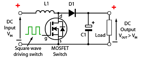
Wrong yet again, either you are very confused, or you want to confuse everyone else or is it both? The circuit diagram you have shown if for a boost converter that boosts the voltage. Hint, look at the webpage address of the image you used. The buck power supply does the opposite.
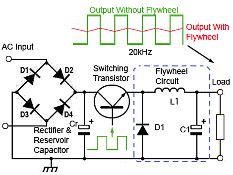
With reference to the circuit diagram below, if we replace the Rectifier & Reservoir Capacitor with a Solar Panel and the Load with a Battery we end up with the basic circuit for an MPPT controller. As you can see the Switching Transistor is between the Solar Panel and the Battery. If the Transistor is switched off the Solar Panel will be disconnected from the battery. A PWM controller is basically the same except that it doesn't have the Flywheel Circuit. For those that want to find out more about buck switch mode power supplies see http://www.learnabout-electronics.org/PSU/psu31.php
Simon
Off grid 24V system, 6x190W Solar Panels, 32x90ah Winston LiFeYPO4 batteries installed April 2013
BMS - Homemade Battery logger https://github.com/simat/BatteryMonitor
Latronics 4kW Inverter, homemade MPPT controller


Comment