MPPT solar controller and LiFePO4 battery for backpacking

Collapse
X
 
  • Time
  • Show
Clear All
new posts
  • Dave C
    Member
    • Apr 2016
    • 66

    #16
    Originally posted by karrak
    If Dave C didn't specify which Genesun model I would assume he got the Pb unit which will charge to 14.2 volts then float at 13.8 volts which is just fine for the battery.
    No, I got the 4-cell Lithium model.

    Originally posted by karrak
    Have you considered that the battery BMS might disconnect the battery from the charge controller when it determines that the battery is full,and not leave the battery on float charge?

    I doubt very much that the BMS would try to drag down the input voltage by shunting current. It will just disconnect the battery terminals from the battery.
    I don't think the BMS disconnects the battery outright at full charge. It switches from constant current, reducing current to a few mA, and expects constant voltage of 14V (not sure if it's actually 14.2V; I'll find out). In their literature, the default CV voltage of the controller is 14.2V.

    Maybe the BMS does briefly disconnect as it switches from CC to CV. I'll see if I can find out.

    Originally posted by karrak
    None of this matters anyway. So what if the BMS disconnects the battery from the charge controller either when the voltage gets too high or if it decides that the charge cycle has finished. Only problem you get is the Genesun giving you a "Battery Overvoltage Fault" and a full battery.
    You suggested earlier that the open panel voltage might damage the battery's BMS. But if the BMS can handle 20 or more Volts, then there might not be a problem.

    Actually, the BMS must be able to handle open panel voltage in the range presented in my scenario, because otherwise, it would fry when you connect it to the controller after having first connected the panel. (Or, maybe a steady diet of this would damage it over time.) Again, this is a question for Bioenno Power.

    I also think that the BMS doesn't disconnect in the presence of any voltage within this range. Otherwise, it would remain open and never accept a charge when you connect it to the controller after having first connected the panel in full sunlight, and this was not the case. The startup sequence with a partially discharged battery was always: 1) connect the panel to the controller; 2) the controller errors and measures panel open voltage at the battery terminals; 3) connect the battery; 4) the controller's status LED immediately goes from error to charging. I never connected a load for fear of damaging my equipment. But it would have been interesting to see if the controller would go back to charging as the load drew power from the battery. I suspect it would have.

    If I'm understanding these things correctly, then it seems to me that either the controller misinterpreted the battery's drop in current as a disconnect, or the BMS did disconnect briefly as it switched from CC to CV. I don't think either of these could be overcome by setting the controller to a different output voltage as Sunking sugested. That is, unless in my limited understanding I'm missing something...
    Last edited by Dave C; 04-14-2016, 11:09 AM.

    Comment

    • Sunking
      Solar Fanatic
      • Feb 2010
      • 23301

      #17
      Originally posted by Dave C
      But the weak link was not necessarily the BMS--based on what you're saying, it was primarily my ignorance of the fact that the controller's output can and must be tuned to the BMS. Too bad Genasun's tech support didn't catch this. If they had, it might have saved us both the hassle of doing a return.
      Some truth to that. Genasun assumes incorrectly you matched the battery and controller correctly. What Genasun does not know, and cannot know is how the BMS works. There is no standard definition of what a BMS is or what it does. Every modular battery manufacture uses a different approach and topology.


      Originally posted by Dave C
      I still think a controller shouldn't allow open panel voltage to pass to the battery terminals under any circumstance--it should handle a no battery condition more gracefully.
      You need to change your way of thinking because it is the nature of the beast. Every MPPT controller I know of does that. This is due to the fact a solar panel is a Current Source and not a Voltage source. With any Current Source when you open the circuit, voltage goes up to supply voltage immediately. That is just the physics and characteristic of a Current Source

      Originally posted by Dave C
      My part number was GV5-Li-14.2V.
      That is just fine and dandy. Again the issue is your BMS. I believe there are two ways to fix this. 1. is lower the voltage of the controller from 14.2 to 13.8 volts. Ignore Karrak when he said that is not a problem because it is a huge problem. Your battery only has one port, or just a positive and negative terminal. When the BMS disconnects, that also mean your gizmo looses power. If the battery had Two Ports, Charge and Load, you would not have to worry about the error.. 2 Add a shunt load to present a load to the controller.

      Try this experiment. Do not use the Load Port on the Controller. Connect a gizmo directly to the battery where you connect the Controller. As for the gizmo, it needs to present a large enough load to keep the charge controller on, and fools the BMS the battery is not fully charged. Bet you a dollar your Controller voltage holds around 14 volts, and the battery BMS does not disconnect. As for the Gizmo it can be as simple as a power resistor, say a 10 watt 15 to 30 Ohm power resistor would be perfect.
      Last edited by Sunking; 04-14-2016, 10:44 AM.
      MSEE, PE

      Comment

      • Sunking
        Solar Fanatic
        • Feb 2010
        • 23301

        #18
        Originally posted by Dave C
        Maybe the BMS does briefly disconnect as it switches from CC to CV. .
        No sir the BMS is not capable of doing that. That is what the Charger does, not BMS. Your Genasun Controller is a CV charger, but also acts like a Constant Current when the battery is low. What is giving you trouble is you do not understand how battery chargers work, and how a BMS works. .

        The Disconnect is your battery BMS was designed to be charged with a conventional Constant Voltage battery charger operation as a Voltage Source In other words a conventional AC powered charger. It was not designed to be charged from MPPT Solar Controller or a Current Source. That means incompatible. Your other Bioenno PWM controller is made to work with that battery as you stated earlier. Based on that I would say just use the Bioenno controller and forget the Genasun. All you are giving up is some panel power.
        Last edited by Sunking; 04-14-2016, 10:58 AM.
        MSEE, PE

        Comment

        • Sunking
          Solar Fanatic
          • Feb 2010
          • 23301

          #19
          Hey I just looked at your battery spec and caught something. Your battery has two ports right? One port for the Charger, and another port for the load equipped with an Anderson Power Pole connector right?

          Does not change much, just confirms what I said. The Charge Port disconnects the battery from charger when the battery BMS detects it is fully charged. The Genasun does not like that and raises an alarm.

          Tell me if this sounds correct when you used the Genasun Controller.. It worked correctly until the battery was charged up, then went into alarm and high voltage. If you had a load connected using power, after some period of time the Genasun alarm would clear and charge the battery again, After the battery charged the Genasun went back into alarm and the cycle repeats itself?

          Is that what you are observing? If so you could use the Genasun and just have to put up with nuisance false alarm. Bet a dollar that is what you observed.

          The issue I take with that design approach is it does not allow you to utilize the solar power when the sun is available and the battery is fully charged. I would prefer to use the solar power when available and not use battery power to extend battery life, wear and tear. My design approach is to utilize all the solar power I can possible use, and only use battery power at night or when there is not sufficient solar power available to supply the load. That is a problem with most solar applications using lithium batteries. Pb systems do not work that way as the solar is always connected. That is the philosophy Genasun uses, but your battery BMS is not designed to support that topology.
          Last edited by Sunking; 04-14-2016, 11:37 AM.
          MSEE, PE

          Comment

          • Dave C
            Member
            • Apr 2016
            • 66

            #20
            Sunking, if an input voltage in the range presented in my scenario were causing the BMS to disconnect due to over voltage, then wouldn't this prevent the battery from ever being charged? I always connected the panel to the controller first in full sunlight, so the BMS always encountered open panel voltage when the partially discharged battery was first connected--granted, at 0A.

            Is it possible that the controller misinterpreted the battery's drop in current when it switched from CC to CV as a disconnect? If, on the other hand, the BMS did disconnect the battery when fully charged, shouldn't the controller handle it more gracefully? Or is it possible that this is the only battery that behaves this way?

            The battery mfr. states that the BMS expects a CV voltage of around 14V (I've asked for an exact value), and the controller mfr. states that the controller's CV voltage is 14.2V. Would you still suggest changing the controller's voltage?

            Not sure if this adds any value, but the generic CC/CV AC charger that came with the battery handles the transition from CC to CV with no problem.

            Comment

            • Dave C
              Member
              • Apr 2016
              • 66

              #21
              Oh, sorry for duplicate info in two posts. I neglected to notice that we had gone into page 2. I thought my prior post was lost.
              Last edited by Dave C; 04-14-2016, 12:15 PM.

              Comment

              • Dave C
                Member
                • Apr 2016
                • 66

                #22
                Originally posted by Sunking
                Hey I just looked at your battery spec and caught something. Your battery has two ports right? One port for the Charger, and another port for the load equipped with an Anderson Power Pole connector right?

                Does not change much, just confirms what I said. The Charge Port disconnects the battery from charger when the battery BMS detects it is fully charged. The Genasun does not like that and raises an alarm.
                The two ports don't provide two different functions, they just provide two different connectors to the same connection points, one for the wall charger and one for ham radio, etc.

                Originally posted by Sunking
                Tell me if this sounds correct when you used the Genasun Controller.. It worked correctly until the battery was charged up, then went into alarm and high voltage. If you had a load connected using power, after some period of time the Genasun alarm would clear and charge the battery again, After the battery charged the Genasun went back into alarm and the cycle repeats itself?

                Is that what you are observing? If so you could use the Genasun and just have to put up with nuisance false alarm. Bet a dollar that is what you observed.
                That would have been valuable information, but as I believed there were major problems with my setup, I never connected a load for fear of damaging it. As you suggested, a resistor would have been the way to go for testing. Unfortunately, there's a lot of inertia to overcome with my brain--I don't improvise well in areas in which I'm not thinking on a day-to-day basis. Isn't your question answered, though, by the fact that each time I connected the partially discharged battery it was charged by the controller? In other words, I agree that if I had left it connected along with a load, it probably would have resumed charging.

                Originally posted by Sunking
                The issue I take with that design approach is it does not allow you to utilize the solar power when the sun is available and the battery is fully charged. I would prefer to use the solar power when available and not use battery power to extend battery life, wear and tear. My design approach is to utilize all the solar power I can possible use, and only use battery power at night or when there is not sufficient solar power available to supply the load. That is a problem with most solar applications using lithium batteries. Pb systems do not work that way as the solar is always connected. That is the philosophy Genasun uses, but your battery BMS is not designed to support that topology.
                Of course, this is how I would hope that it works. I don't know enough to assume that the Bioenno Power battery wasn't designed to work this way. You do raise some questions that I will ask, though.

                Originally posted by Sunking
                What is giving you trouble is you do not understand how battery chargers work, and how a BMS works.
                Obviously. That's why I'm consulting with you guys. I'm very appreciative of the thorough answers you have provided.

                Originally posted by Sunking
                The Disconnect is your battery BMS was designed to be charged with a conventional Constant Voltage battery charger operation as a Voltage Source In other words a conventional AC powered charger. It was not designed to be charged from MPPT Solar Controller or a Current Source. That means incompatible. Your other Bioenno PWM controller is made to work with that battery as you stated earlier. Based on that I would say just use the Bioenno controller and forget the Genasun. All you are giving up is some panel power.
                The explanation I received from Bioenno back in September is that the AC charger is a CC/CV charger--that it initially provides CC and then switches to CV. Also, Bioenno now offers an MPPT controller that is compatible with their batteries. I'm going to ask them to review this thread if they have time and give me some feedback. It's a lot to ask, and I don't assume anything, but Kevin has provided such great communication and service to date, I wouldn't be surprised if he takes the time to do this.

                Thank you so much for sharing your knowledge and years of experience with me.

                Comment

                • jflorey2
                  Solar Fanatic
                  • Aug 2015
                  • 2331

                  #23
                  Originally posted by Dave C
                  But the weak link was not necessarily the BMS--based on what you're saying, it was primarily my ignorance of the fact that the controller's output can and must be tuned to the BMS.
                  It doesn't need to be. One of the primary functions of a charge controller is to prevent the voltage from exceeding a limit. If it does that, it's not working. If it is just that one, then it's defective. If they all do that, then it's a design flaw.

                  A BMS should NEVER be required to "sink" power to keep voltages under a limit, and does not need to be "tuned" to a given charge controller. BMSes are designed to protect batteries, and in some cases provide other services like balancing. They are not charge controllers. If the BMS is cutting out at the right voltage, it is doing its job. If the charge controller is providing a charge voltage that is safe for the battery, then it is doing its job.


                  Comment

                  • Sunking
                    Solar Fanatic
                    • Feb 2010
                    • 23301

                    #24
                    Originally posted by Dave C
                    The two ports don't provide two different functions, they just provide two different connectors to the same connection points, one for the wall charger and one for ham radio, etc.
                    Are you aboslutely certain about that? There is no other reason to have two ports.
                    MSEE, PE

                    Comment

                    • Dave C
                      Member
                      • Apr 2016
                      • 66

                      #25
                      Originally posted by Sunking
                      Are you aboslutely certain about that? There is no other reason to have two ports.
                      Yes, that's what the mfr. told me, and I verified.

                      Comment

                      • Sunking
                        Solar Fanatic
                        • Feb 2010
                        • 23301

                        #26
                        You read 18 volts on both ports?

                        No LFP battery would survive that, it would explode into flames before it ever reached 18 volts. Something is not right. Only way that can happen is if the battery disconnected on a Genasun controller. .

                        Something no one has caught yet, but Genasun is the only controller on the narket that requires the panel be connected before the battery. Do that to any other controller and it will let the magic smoke out. When you connected the panel first, what did you observe?

                        I bet the voltage went high and in alarm? Then when you connected the battery went normal, charged,, then went back into alarm when the battery was charged? Is that what happens?
                        Last edited by Sunking; 04-14-2016, 05:59 PM.
                        MSEE, PE

                        Comment

                        • karrak
                          Junior Member
                          • May 2015
                          • 528

                          #27
                          Originally posted by Dave C
                          I don't think the BMS disconnects the battery outright at full charge. It switches from constant current, reducing current to a few mA, and expects constant voltage of 14V (not sure if it's actually 14.2V; I'll find out). In their literature, the default CV voltage of the controller is 14.2V.

                          Maybe the BMS does briefly disconnect as it switches from CC to CV. I'll see if I can find out.
                          I would think that the BMS will only disconnect the battery when the voltage on any of the individual cells goes out of its safe operating range, probably something like 2.5 to 3.65 volts. If the battery is balanced and the cells all have the same capacity this will equate to an overall battery voltage of 10 to 14.6 volts.which is what their documentation implies. They specify a charge voltage of 14.6 volts.

                          When you are charging an LFP battery to start with the battery will take as much current as the charge controller can give it within its specified limits. If you are charging from solar this is as much current as the solar panel can supply and varies depending on the amount of sunlight. With other power supplies this is usually a fixed current and is known as CC. The battery voltage will rise as you charge. When the battery reaches the cutoff voltage the charge controller will start to limit the current going into the battery to keep the battery voltage at the cutoff voltage. This is known as CV charging. With an LFP battery the charge current will taper off to zero.

                          For lithium batteries the charge controller should never let its output voltage go above the programmed cutoff voltage!

                          What I think is happening with the Genasun is that it will not let the current drop to zero, because of this the output voltage will continue to rise until the BMS in the battery does its job and detects too high a voltage and disconnects the battery to protect it. It is fortunate the battery had the inbuilt BMS, without it it is very likely that your battery would have been damaged.

                          You suggested earlier that the open panel voltage might damage the battery's BMS. But if the BMS can handle 20 or more Volts, then there might not be a problem.

                          Actually, the BMS must be able to handle open panel voltage in the range presented in my scenario, because otherwise, it would fry when you connect it to the controller after having first connected the panel. (Or, maybe a steady diet of this would damage it over time.) Again, this is a question for Bioenno Power.

                          I also think that the BMS doesn't disconnect in the presence of any voltage within this range. Otherwise, it would remain open and never accept a charge when you connect it to the controller after having first connected the panel in full sunlight, and this was not the case. The startup sequence with a partially discharged battery was always: 1) connect the panel to the controller; 2) the controller errors and measures panel open voltage at the battery terminals; 3) connect the battery; 4) the controller's status LED immediately goes from error to charging. I never connected a load for fear of damaging my equipment. But it would have been interesting to see if the controller would go back to charging as the load drew power from the battery. I suspect it would have.
                          I agree with you

                          I don't think either of these could be overcome by setting the controller to a different output voltage as Sunking sugested. That is, unless in my limited understanding I'm missing something...
                          I don't think you have missed anything. If the voltage at the connector is less than 14.6 volts and greater than 10 volts the BMS will keep the battery connected to the outside world.

                          Simon

                          Off grid 24V system, 6x190W Solar Panels, 32x90ah Winston LiFeYPO4 batteries installed April 2013
                          BMS - Homemade Battery logger https://github.com/simat/BatteryMonitor
                          Latronics 4kW Inverter, homemade MPPT controller
                          Last edited by karrak; 04-14-2016, 08:25 PM.
                          Off-Grid LFP(LiFePO4) system since April 2013

                          Comment

                          • karrak
                            Junior Member
                            • May 2015
                            • 528

                            #28
                            Originally posted by Sunking
                            You need to change your way of thinking because it is the nature of the beast. Every MPPT controller I know of does that. This is due to the fact a solar panel is a Current Source and not a Voltage source. With any Current Source when you open the circuit, voltage goes up to supply voltage immediately. That is just the physics and characteristic of a Current Source
                            This is absolute rubbish. It is the MPPT controllers job to take the output power from the solar panels and convert it to a form that is acceptable and safe for charging a battery. An MPPT controller is basically a buck switched mode power supply and can easily be designed to keep the output voltage below what it is programmed to be. The Genasun is the only MPPT controller that I have heard of that will let its output voltage go above the programmed output voltage. I am sure it is to do with the fact that the Genasun gets it power from the solar panels and not from the battery.

                            Simon

                            Off grid 24V system, 6x190W Solar Panels, 32x90ah Winston LiFeYPO4 batteries installed April 2013
                            BMS - Homemade Battery logger https://github.com/simat/BatteryMonitor
                            Latronics 4kW Inverter, homemade MPPT controller
                            Off-Grid LFP(LiFePO4) system since April 2013

                            Comment

                            • Sunking
                              Solar Fanatic
                              • Feb 2010
                              • 23301

                              #29
                              Originally posted by karrak
                              This is absolute rubbish.
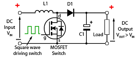
                              Try it and see what happens. Be sure there is bright sun out, and disconnect the battery and see what happens. If you had any clue how Buck Converters work you would know that. Below is the Buck Converter in its simplest form. If the FET looses it reference signal which is what happens if the battery is disconnected, the FET shuts off and the Input is directly connected to the output through L1 and a forward biased diode. .

                              Last edited by Sunking; 04-14-2016, 10:45 PM.
                              MSEE, PE

                              Comment

                              • Dave C
                                Member
                                • Apr 2016
                                • 66

                                #30
                                Originally posted by Sunking
                                You read 18 volts on both ports?
                                If by "ports" you mean both the barrel connector and the power pole connector that are soldered to the battery, then yes.

                                Originally posted by Sunking
                                No LFP battery would survive that, it would explode into flames before it ever reached 18 volts. Something is not right. Only way that can happen is if the battery disconnected on a Genasun controller.
                                I agree that the BMS disconnected the battery from the controller first, and this caused the the voltage increase and alarm at the controller. I don't think we've been able to figure out why, though. My wild guess at this point is that the BMS didn't like how the controller handled the fully charged battery. Maybe it was something like the controller taking longer than the BMS expected to back down current as the system transitioned from CC to CV? Is that possible? If not, then maybe something similar? Whatever it was, it seems like the BMS gave the controller a few chances to get it right, because the sequence at the end was actually: 1) LED shows "charged" briefly; 2) LED changes to error, and stays there for about 30 sec.; 3) the LED changes from error to charging; 4) repeat steps 1 - 3 for a total of 4 times; 5) the LED remains permanently in error status. Because the number of repeats equaled the number of cells, maybe it had something to do with the internal balancing circuit? A strike against that hypothesis is that there was no such error cycle when the battery was charged using the wall charger or with the Bioenno PWM controller. Once the battery charged, the LED on the wall charger switched from CC to CV and stayed there, and once the status on the PWM controller showed "charged", it remained there. Again, I'm grasping at straws in unfamiliar territory.

                                Originally posted by Sunking
                                When you connected the panel first, what did you observe? I bet the voltage went high and in alarm? Then when you connected the battery went normal, charged,, then went back into alarm when the battery was charged? Is that what happens?
                                Yes, that's pretty much what I observed. I've posted this a few times, but in posting again, maybe I'll see something different or word it more accurately. 1) nothing connected to the controller; 2) connect panel to controller --> immediate alarm and high voltage at controller's battery terminals; 3) connect battery to controller --> LED changes immediately from alarm to charging; 4) battery reaches full charge --> first, controller shows charged briefly, then alarm and high battery terminal voltage return. Sure enough, writing out number 4 led to the bulk of my main paragraph above.

                                FYI, I'm in contact with a Genasun user who always connects the battery first.

                                I think a good test would be to get a new GV-5 and a new battery and see if the same thing happens.

                                It would be a lot easier to just stick with the PWM controller that I have...
                                Last edited by Dave C; 04-15-2016, 12:57 AM.

                                Comment

                                Working...