Announcement

Collapse
No announcement yet.

Diodes and bypass diodes

Collapse
X
 
  • Filter
  • Time
  • Show
Clear All
new posts

  • #31
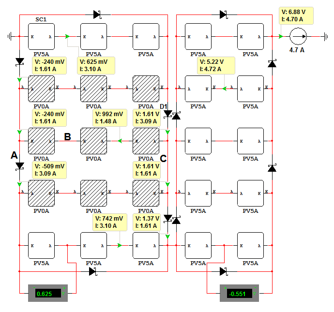
    hi lonewolf, thanks for your results and experiments, they helped to see ways to do it, and ways to avoid. i went for non interlaced setup, so that if a cell gets shaded then the bank encompassed by the bypass diode, typically 8 to 12 cells, will get bypassed by the one diode. this will allow the large panels to be divided into about 6 parts each for shading purposes.

    the interlaced designs you have posted will work, but seems some strings will have to pass 2x the current at times, and the rest of the time is hard to calculate. non interlaced seems easier to deal with

    Comment


    • #32
      Maybe I can help you with this page. Everything you always wanted to know about bypass diodes. http://www.avdweb.nl/solar-bike/bypass-diodes.html

      Here is an example which is simulated in Multisim.


      I prefer these bypass diodes,
      SBR30U30CT
      SBR20U40CT

      Comment


      • #33
        Originally posted by avandalen View Post
        Maybe I can help you with this page. Everything you always wanted to know about bypass diodes. http://www.avdweb.nl/solar-bike/bypass-diodes.html

        Awesome, thanks.

        So, how's the solar bike project ?
        Powerfab top of pole PV mount (2) | Listeroid 6/1 w/st5 gen head | XW6048 inverter/chgr | Iota 48V/15A charger | Morningstar 60A MPPT | 48V, 800A NiFe Battery (in series)| 15, Evergreen 205w "12V" PV array on pole | Midnight ePanel | Grundfos 10 SO5-9 with 3 wire Franklin Electric motor (1/2hp 240V 1ph ) on a timer for 3 hr noontime run - Runs off PV ||
        || Midnight Classic 200 | 10, Evergreen 200w in a 160VOC array ||
        || VEC1093 12V Charger | Maha C401 aa/aaa Charger | SureSine | Sunsaver MPPT 15A

        solar: http://tinyurl.com/LMR-Solar
        gen: http://tinyurl.com/LMR-Lister

        Comment


        • #34
          Solar bike project

          Originally posted by Mike90250 View Post
          Awesome, thanks.

          So, how's the solar bike project ?
          Dear Mike,

          It is difficult to get the special parts, light sandwich panels, diodes etc. Now I start with the PV panels.

          Albert

          Comment


          • #35
            avandalen, thanks for the good tutorial on diodes. i do not have the multisim program but it appears in your example that you are still losing 12 cells of power rather than just the 9 shaded. it seems you could use less diodes by using 1 for each group of 3 cells, and 1 for each group or 2 in the second group. am wondering if you could show a similar image having only noninterlaced bypass diodes.

            i can see that if only the bottom 3 cells below the 9 shaded ones were shaded then a single bypass diode connected like you have will bypass just those 3 cells, however i believe you are losing 12 in example when just losing 9 would be optimal for your needs.

            Comment


            • #36
              Current trough the top en bottom string is 3.1A instead of 4.7A.

              Originally posted by RifRaf View Post
              avandalen, thanks for the good tutorial on diodes. i do not have the multisim program but it appears in your example that you are still losing 12 cells of power rather than just the 9 shaded. it seems you could use less diodes by using 1 for each group of 3 cells, and 1 for each group or 2 in the second group. am wondering if you could show a similar image having only noninterlaced bypass diodes.

              i can see that if only the bottom 3 cells below the 9 shaded ones were shaded then a single bypass diode connected like you have will bypass just those 3 cells, however i believe you are losing 12 in example when just losing 9 would be optimal for your needs.
              Thanks for you input
              Using 1 bypass diode for each group of 3 cells is not feasible because of wiring.

              Here is my new text on the webite: with the explanation of the higher voltage loss:

              This example has a remarkable current distribution trough the solar cells and bypass diodes. IA = 3.09A, IB = 1.48A and IC = 1.61A. The voltage loss is higher than expected and can

              Comment


              • #37
                hi i'm bambi and im here to learn

                Comment


                • #38
                  hi

                  great stuff, im doing a panel and need the most efficient wire up for diodes. also will 100v 16 amp be ok and how do you wire the 3 leg to-220 ones

                  martin

                  Comment


                  • #39
                    Originally posted by martinjsto View Post
                    great stuff, im doing a panel and need the most efficient wire up for diodes. also will 100v 16 amp be ok and how do you wire the 3 leg to-220 ones

                    martin
                    Hi Martin

                    Perhaps I will use smd bypass diodes, I have to figure it out. The bypass diode wiring is very short, closed to the solar cells with thin solar ribbon cable. Because the PV panel loss with shadow is already high, low diode wire resistance brings not much.

                    Comment


                    • #40
                      martin hi, to wire up the to220 the easiest way i found was. Chop off the center lead of the 3, join the two outside legs together to double the current, solder some bus wire to the tab on the top of diode for the other lead. solder the big tab end to the positive end of your string, solder the 2 joined pins to the negative end.

                      if you install the diodes at the end of the strings, they will join the strings together at the opposite end to where they the strings are joined with bus wire, keeps things even more stable for encapsulation, and easy to get at later

                      be aware that most diodes on ebay and that i have seen posted here recently are not suitable for use with 6x6 cells, you want diodes rated at over 15a and more voltage than your entire panel array, as i am using 8A cells in a 60V string these are more suitable. http://www.onsemi.com/pub_link/Colla...R20100CT-D.PDF rated at 100v and 20A if the diodes are tied together.

                      the instructions above relate to these diodes, modify if your diode has different pinouts.

                      Comment


                      • #41
                        martin hi, to wire up the to220 the easiest way i found was. Chop off the center lead of the 3, join the two outside legs together to double the current,NOT TRUE it will give about 50% extra at best..

                        Comment


                        • #42
                          hi john p, well even 15a will be heaps, as the total current is 7.5 - 8A max with peaks of 10A at short circuit current, so still 50% tolerance. however after studying the datasheet they appear pretty well matched and should perform up to the 20A constant rating with decent heatsinking, am using about 50mm of 5mm bus wire on each end of the diode to connect the cells between strings. no need to explain as the difference does not matter, but 5A seems alot to lose from a parallel configuration of 2 matched diodes in the same package. guess this needs testing, will have to wire a few strings up in parallel to test at 20A, have several diodes that have not been modified

                          Comment


                          • #43
                            even if they are matched it wont happen one will always take the lions share,, same happens if you look at audio amp designs using bipolar output transistors , there arew always ballancing resistors ,, And they are necessary even if you use very close matched sets of transistors.. To balance the load across the 2 diodes you would need to use 2x .1 ohm resistors.. It difficult to verify if both diodes are carrying half the current,, and it will vary with temperature.

                            Comment


                            • #44
                              Hi and thanks for the follow up. so we loose 50% of current capacity of the diode by joining legs together, and they need to be installed at the end of the strings, right?
                              seems with also using resistors as john sugest that power loss will be quite high and also heat will be created from the resistor, wont it be better just to use the inline diode as you see on ebay? can you get them rated at 20 amp? i was thinking of locating them on the rear of the panel as im installing cooling and strenghtening rails of aluminium angle underneith the panel. i could connect them to the rails, encapsulate them by painting with sylgard after main encapsulation has set, and they will act as a heat sink, i thought to encapsulate the rails into the backing (insulated of course), the rails will also have to be insulated from each other i guess, whats your thoughts?
                              has anyone got a diagramme of the diode positions i have a couple but am after the best layout protecting strings of cells.
                              thanks for any help

                              Comment


                              • #45
                                the loss through a .1 ohm resistor is very small. but if it was me I would not be using a dual package diode like that. it far better to be using a single diode

                                Comment

                                Working...
                                X