12v solar system reveiw and advice please

Collapse
X
 
  • Time
  • Show
Clear All
new posts
  • baddancer
    Junior Member
    • Mar 2017
    • 17

    12v solar system reveiw and advice please

    Hello
    New member but long time lurker.
    I was hoping to get some feedback on my sytem and any input would be appreciated.

    1 have a 12v system for my off grid cabin in the gulf islands, B.C.

    1x120 w panel
    4x60w panels

    My plan is as follows.

    All panels will be wired parallel using a home made combiner box that is water proof and sealed.
    10 gauge wire from panels to combiner box. My estimate is that in parralel, i will be getting about 20 amps

    From combiner box, I will run 8 gauge to a 30 amp thermal breaker from Blue Sea.
    The wire run is approx 20-25 feet max.
    From breaker to charger controller, I will be running 8 gauge again unless my charger controller terminals will not take an 8 gauge wire and then I will use 10 gauge. I currently have a 30 amp pmw enerwatt that seems to be working fine with the one panel that I am already using.

    From Charge controller to battery bank, I will run 8 gauge wire. Again, I will use 10 if 8 will not fit my CC. I will need another fuse here I am told and not sure what to use.

    I have just purchased 2 6v golf batteries. I have a 1/0 bridge cable that I will use.
    I have a samlex 600w pure sine inverter that I plan on using to run my small mini fridge.
    I have used a killowat meter on it with regular conditions such as leaving the door open etc..i have a teenager so i know how a fridge is really used.
    It pulls 50 watts while compressor is running and seems to run about 6-7 hours in a 24 hour period. I plan on using a timer at night to limit usage.

    My questions are
    1. Do i need to fuse each panel prior to my combiner box or is the 30 amp breaker enough.
    2 What size of wire if best from my batteries to inverter.?
    3. Can I use regular 8 awg outdoor if all my terminals are sealed and water proof.

    I am sure I missed a few things but that is my starting point as this juncture of my journey.

    Looking forward to any input and ideas.

    Thanks


    Last edited by baddancer; 03-25-2017, 02:53 PM.
  • Sunking
    Solar Fanatic
    • Feb 2010
    • 23301

    #2
    Originally posted by baddancer
    My questions are
    1. Do i need to fuse each panel prior to my combiner box or is the 30 amp breaker enough.
    2 What size of wire if best from my batteries to inverter.?
    3. Can I use regular 8 awg outdoor if all my terminals are sealed and water proof.
    A1. Yes. You crossed the line when you go over two parallel strings. With your PWM Controller, using a prime number of panels (5), and mixed bag of panels you have no choice other than 5 in parallel. The fuses need to be at the panel output terminals.

    A2. Depends on length. You wil need a 60 - Amp Fuse on the battery so the minimum is #6 AWG but only good for 6-feet one-way. Otherwise larger. Look at this Table. Keep your losses to less than 3%.

    A3. You can use any size you want providing it meets the minimum current and voltage drop requirement. If you mean between the panels and combiners is quite a bit of over kill as you are talking 10 amp fuse on the 120 watt panels and 5 amp fuses on the 60 watl panels. . Minimum wire size is determined by the fuse. But there s one catch with Low Voltage and that would be Voltage Loss. Keep it less than 3%. Again see the Table. * AWG meets and exceeds the requirement. So YES

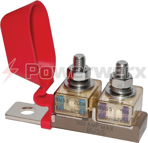
    Roughly this is what you want to do with your battery fuses. One facing the Controller, and one facing the Inverter. You will need a 30 amp facing Controller, and a 60-amp facing Inverter. They are installed directly on the Battery Term Post.


    Here are the fuse blocks you want, a dual Fuse Block from Blue Sea
    Last edited by Sunking; 03-25-2017, 05:27 PM.
    MSEE, PE

    Comment

    • baddancer
      Junior Member
      • Mar 2017
      • 17

      #3
      Thanks for the response.
      I think I understand everything except for the fuses at the panel output boxes.
      Can anyone e explain why I need to have a fuse for each panel before the combiner box and why a beaker before the charge controller is not enough?
      Therw is a 5 into 1 mc4 connector available.
      Is that not recommended and why ?
      Thanks again !
      IMG_4796.PNG
      Attached Files

      Comment

      • Sunking
        Solar Fanatic
        • Feb 2010
        • 23301

        #4
        Originally posted by baddancer
        Can anyone explain why I need to have a fuse for each panel before the combiner box and why a beaker before the charge controller is not enough?
        Because you used more than two strings. You created the situation that now requires you to use fusses on each string. Two strings or less requires no fuses anywhere between the panels and controller. A single string or even two strings combined cannot produce enough fault current to damage the wiring on a faulted string. However when you add the 3rd, 4,th, and 5th string, if a string faults, you now have all the other strings dumping their fault current into the faulted string with more than enough fault current to damage the wiring and start a fire.

        A fuse only protects the downstream fault current on the wire it is connected to. The fuse on the output feeder of the combiner only protects the wire between the combiner and charge controller. It cannot possible protect any of the individual string wires behind it upstream.

        Note what is going on in the diagrams I provided you above. They use 2 x 200 watt panels wired in series. There are no fuses required and uses small inexpensive 14 AWG conductor. A 200 watt panel generates about 8 to 9 amps of current at Isc which cannot damage 14 AWG wire as 14 AWG wire can safely handle up to 20 amps of current all day long. You cannot do any of that because you have a PWM Controller which forces you to use very expensive low voltage battery panels wired in parallel.

        Your 320 watts of panels will generate roughly 20 amps of battery charging current which at 12 volts = 240 watts. You then get hit hard with wire and material cost. For quite a bit less money you could have bought a single 240 watt Grid Tied Panel with a 20 Amp MPPT Controller and had the exact same 20 amps of charge current. It would have saved you $200 to $400.

        Now having said all that you are not applying for permits or have to pass inspection. Basically no one cares what you do or if you burn down your cabin. It boils down to what you can live with and what makes you sleep better at night. If you had to apply for permits and pass inspection you would have to use fuses and you could not use a DIY combiner. So it is all kind of a moot point. In a system that requires an Inspection you cannot pick and choose what codes and practices you wil or will not follow.
        Last edited by Sunking; 03-26-2017, 12:26 PM.
        MSEE, PE

        Comment

        • baddancer
          Junior Member
          • Mar 2017
          • 17

          #5
          Thank you for the response. This is exactly why I have posted up here. Great knowledge !
          I have now re thought and planned the system. I will be using a water proofed combiner box with a fuse for each panel.
          Thanks again

          Comment

          • B-17
            Member
            • Aug 2016
            • 40

            #6
            Breakers are even better than fuses. The MidNite MNPV6 and five 15A breakers will be a nicer, neater choice, plus it saves time and is reasonably priced.

            Comment

            • baddancer
              Junior Member
              • Mar 2017
              • 17

              #7
              Yes thanks. i was thinking breaker as well. One question I had about fuses is they are not suppose to be opened under load. How does one do that ? Maybe a stupid question.
              Wait for a cloudy day ? Kidding of course. Also breaker size ? If my panel is putting out around 6-7 amps then I would calculate the ampacity by 1.56 ?
              In my case 6-7 amps would put my at 11 at 10.9 amps. Is a 10 amp breaker/fuse ok or do I bump up to 15 ? I am running 10 gauge from array to breaker at approx 4-6 feet.
              My calculations would indicate that 15 will be the right choice for the 120 watt panel and a 10 will be right for the 60 watt panels.

              Comment

              • B-17
                Member
                • Aug 2016
                • 40

                #8
                10 or 15A will be fine for everything. Your choice. The breaker size is mainly to protect the wire according to size. The back feed rating on the modules is likely 15A

                Comment

                • baddancer
                  Junior Member
                  • Mar 2017
                  • 17

                  #9
                  Updated install info.
                  i ended up installing the midnight solar breaker box with 15a breakers.
                  i currently have a 120, 60, and 100 w panels connected in parralel.
                  8 gauge wire from combiner box to charge controller. Hooked up my 2 golf cart batteries with 6 gauge wire from my batteries to inverter with a 100 amp battery post fuse.
                  All good so far.
                  Plugged in the fridge to the 600 w samlex pure some inverter. Did not work. Seemed to overload the inverter. Faaaakkkkk!
                  I think the inverter is not what it says it is.
                  When I hooked up my killawatt meter to the fridge, it showed only a 900 w spike on start up. The inverter is suppose to Handle 1200 peak. Also, the inverters fan starts up even when not connected to any load. This can not be correct.
                  I am now sourcing other pure sine inverters.

                  Feedback always welcome.

                  Comment

                  • Mike90250
                    Moderator
                    • May 2009
                    • 16020

                    #10
                    Plugged in the fridge to the 600 w samlex pure some inverter. Did not work. Seemed to overload the inverter. Faaaakkkkk!
                    I think the inverter is not what it says it is.
                    When I hooked up my killawatt meter to the fridge, it showed only a 900 w spike on start up
                    most meters, including the kill-a-watt, do not actually measure (or specifically - CANNOT) measure the starting surge of a fridge. I know of VERY FEW 600w inverters (ok, NONE) that reliably start a standard fridge.

                    Try to find a local electrician who actaully has a "Peak Reading AC AMPS" meter, pay him $60 for a 5 minute visit to measure the actual startup surge. Or spend the $350+ needed to purchase your own sub second peak reading meter.

                    Powerfab top of pole PV mount (2) | Listeroid 6/1 w/st5 gen head | XW6048 inverter/chgr | Iota 48V/15A charger | Morningstar 60A MPPT | 48V, 800A NiFe Battery (in series)| 15, Evergreen 205w "12V" PV array on pole | Midnight ePanel | Grundfos 10 SO5-9 with 3 wire Franklin Electric motor (1/2hp 240V 1ph ) on a timer for 3 hr noontime run - Runs off PV ||
                    || Midnight Classic 200 | 10, Evergreen 200w in a 160VOC array ||
                    || VEC1093 12V Charger | Maha C401 aa/aaa Charger | SureSine | Sunsaver MPPT 15A

                    solar: http://tinyurl.com/LMR-Solar
                    gen: http://tinyurl.com/LMR-Lister

                    Comment

                    • baddancer
                      Junior Member
                      • Mar 2017
                      • 17

                      #11
                      Thanks Mike. I will source a new inverter. Doea anyone have experience with the inverter fan running without anything connected to it ? Seem kind of weird. Just turning it on runs the fan.

                      Comment

                      • jflorey2
                        Solar Fanatic
                        • Aug 2015
                        • 2331

                        #12
                        Originally posted by baddancer
                        Thanks Mike. I will source a new inverter. Doea anyone have experience with the inverter fan running without anything connected to it ? Seem kind of weird. Just turning it on runs the fan.
                        Better inverters run the fan only when needed. Running the fan full time results in rapid dust buildup on the heat exchanger surfaces, leading to early failure.

                        Comment

                        • J.P.M.
                          Solar Fanatic
                          • Aug 2013
                          • 14920

                          #13
                          Originally posted by jflorey2
                          Better inverters run the fan only when needed. Running the fan full time results in rapid dust buildup on the heat exchanger surfaces, leading to early failure.
                          If better inverters run the fan only when needed, it may be to save energy rather than the rate of dust accumulation which, for most applications tends to be either mostly constant as f(time) or may (if done correctly) actually show some decrease in accumulation rate as f(time) due to higher mass velocity flow rates having a bit of a scouring effect - not unlike the difference often observed between the bottom of fast running streams vs. slow running streams.

                          The fouling layer(s) on HX's, both natural convection and forced convection designs in both how the fouling layer may affect heat transfer and how fast the fouling layer accumulates can be quite complicated, but unless the forced convection flow rate is so small as to be useless (technically when something called the Nusselt number is <~ 4 to 6 or so depending on a lot of particulars), the cooling film coefficient enhancement due to forced convection is always more than enough to allow the equipment to run cooler, unless the fouling is so bad as to limit the mass flow rate by obstruction and increased pressure drop.

                          Basically, HX fouling for any particular fluid (in this case air) is not so much a function of mass flow rate as a function of time, and, if/when mass flow velocities are a factor, more flow is usually better in terms of both the net effect of enhanced heat transfer keeping the equipment cooler as well as probably keeping the equipment less fouled over time. Whether or not the benefits of forced convection cooling are enough to overcome the drawbacks in terms of design, safety, maintenance, cost and other factors is one example of why engineers make the big bucks by balancing competing priorities.

                          Comment

                          • jflorey2
                            Solar Fanatic
                            • Aug 2015
                            • 2331

                            #14
                            Originally posted by J.P.M.
                            If better inverters run the fan only when needed, it may be to save energy rather than the rate of dust accumulation which, for most applications tends to be either mostly constant as f(time) or may (if done correctly) actually show some decrease in accumulation rate as f(time) due to higher mass velocity flow rates having a bit of a scouring effect
                            That may well be true, and even the small amount of power a fan takes can add up.

                            When SolarGuppy redesigned the first (terrible) Trace grid tie inverters, putting in variable speed fans, whose speed was proportional to temperature rise, was something he considered very important to reduce the accumulation of crud within the inverter. He did it by PWMing the power to the fans, which resulted in an odd "dit dit dit" sound from the fans when running at low speed. But it worked.


                            Comment

                            • J.P.M.
                              Solar Fanatic
                              • Aug 2013
                              • 14920

                              #15
                              Originally posted by jflorey2
                              That may well be true, and even the small amount of power a fan takes can add up.

                              When SolarGuppy redesigned the first (terrible) Trace grid tie inverters, putting in variable speed fans, whose speed was proportional to temperature rise, was something he considered very important to reduce the accumulation of crud within the inverter. He did it by PWMing the power to the fans, which resulted in an odd "dit dit dit" sound from the fans when running at low speed. But it worked.

                              For all the non linearities involved and the lack of knowledge of heat transfer most folks exhibit, it's usually better to not try to get fancy. Like good food, enough is usually a feast and heat transfer design probably fits that mode better than some other disciplines. More complication of the type you write of is mostly a waste and usually only serves to complicate things needlessly with the usual result of not much more than more stuff to break down and service.

                              Forced convection is usually about an order of magnitude or two more effective than nat. convection anyway, and that is usually what can make forced convec. more cost effective if done in a knowledgeable way, and usually justifiable if reliable designs can be done for the right economics. KISS applies. Both modes, natural and forced convection have their place. The tradeoff is more surface area often meaning more material cost and footprint (for nat. conv.), vs. more pumping cost, more maint. and noise and more complexity (forced convec.).

                              Comment

                              Working...