Lessons learned from Self Install in Milpitas CA

Collapse
X
 
  • Time
  • Show
Clear All
new posts
  • foo1bar
    Solar Fanatic
    • Aug 2014
    • 1833

    #16
    Originally posted by Nephi
    Since I had run the earth grounding electrode out of the DC Disconnect, against the wall, and to the house, the AC conduit didn't need bonding. But whatever, I did the rework, and now it's there. If the earth grounding electrode was in the conduit, it would have needed the bond, even if it is <250V. So be it.
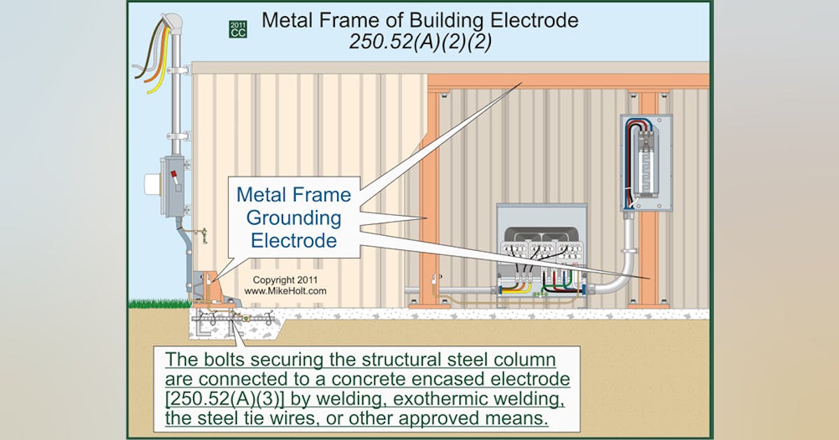
    Voltage of the other wires in the conduit is irrelevant. You want to bond it on both ends because if you don't the conduit acts as a inductive choke. You want a lightning strike to the equipment to be routed to ground through the ground wire and to have as little resistance on that path to ground as possible (since the electricity takes all paths in parallel - so the one with least resistance gets the most current)
    When you put a steel tube around the ground wire, it now has a magnetic choke effect - and that effect at high frequency is significant. (and lightning is very high frequency compared to your 60Hz house wiring)

    Here's a reference:


    (I'm sure there are other places too if you search for "GEC inductive choke conduit"
    Comment

    • DanKegel
      Banned
      • Sep 2014
      • 2093

      #17
      Congratulations!

      Comment

      • Nephi
        Junior Member
        • Oct 2015
        • 25

        #18
        Foo1bar - Thanks for the deep dive explanation!

        Comment

        • FNG AZ
          Junior Member
          • Jun 2015
          • 59

          #19


          Originally posted by Nephi
          Update - The City inspector signed off! My solutions were accepted by him with visual inspection, etc. Signed Permit has been scanned and sent to Utility for approval. Very Exciting!

          Since I had run the earth grounding electrode out of the DC Disconnect, against the wall, and to the house, the AC conduit didn't need bonding. But whatever, I did the rework, and now it's there. If the earth grounding electrode was in the conduit, it would have needed the bond, even if it is <250V. So be it.

          Today I'm giving a casual presentation to an open group describing what I've learned installing my one PV. Should be fun!
          Thanks again for everyone's input and ideas. I hope this "blog" has helped others make decisions.
          QUOTE=foo1bar;n301896]

          Voltage of the other wires in the conduit is irrelevant. You want to bond it on both ends because if you don't the conduit acts as a inductive choke. You want a lightning strike to the equipment to be routed to ground through the ground wire and to have as little resistance on that path to ground as possible (since the electricity takes all paths in parallel - so the one with least resistance gets the most current)
          When you put a steel tube around the ground wire, it now has a magnetic choke effect - and that effect at high frequency is significant. (and lightning is very high frequency compared to your 60Hz house wiring)

          Here's a reference:
          http://ecmweb.com/code-basics/ground...nding-part-3-3

          (I'm sure there are other places too if you search for "GEC inductive choke conduit"[/QUOTE]


          Ya grounding and bonding are very tricky sometimes. Lots of confusing stuff out there. This got even more complicated with transformer less inverters. BTW its the GEC Grounding Electrode Conductor and EGC Equipment Grounding Conductor. The SMA -22 Series only has a EGC. No GEC connection. SO that inverter should NOT be tied to any ground rods/ufers.

          For lighting protection you need a completely different system! and that 10 or 12 gauge EGC from the array will evaporate when it sees the 100,000 amps that a strike can generate. It will last just long enough to cause side flashes!
          30 SW310XL SB7700
          20 SW320XL SB5000

          Comment

          • foo1bar
            Solar Fanatic
            • Aug 2014
            • 1833

            #20
            Originally posted by FNG AZ

            Ya grounding and bonding are very tricky sometimes. Lots of confusing stuff out there. This got even more complicated with transformer less inverters. BTW its the GEC Grounding Electrode Conductor and EGC Equipment Grounding Conductor. The SMA -22 Series only has a EGC. No GEC connection. SO that inverter should NOT be tied to any ground rods/ufers.
            The inverter should absolutely be tied to a ground rod/ufer.
            Every EGC in your house including the one for the inverter should be tied together at the main panel. And that should be tied to the GEC which goes to the ground rod/ufer/water pipes.

            The GEC that is grounding the rails and panels' frames is now often the same wire as the AC EGC for the inverter.
            In this case, since it's a ground wire going up to the panels it must be a DC GEC.

            For lighting protection you need a completely different system! and that 10 or 12 gauge EGC from the array will evaporate when it sees the 100,000 amps that a strike can generate. It will last just long enough to cause side flashes!
            IMO whether it's going to "evaporate" in the few microseconds of high current. It's not mS, but 50-70uS per stroke (Of course there are multiple strokes in any strike that you see)
            But that debate is irrelevant to the point of this - which is to meet code requirements.

            From what I can tell, where those code requirements came from is from inductive choke - which is an understandable reason.

            Comment

            • FNG AZ
              Junior Member
              • Jun 2015
              • 59

              #21
              That inverter only has an EGC. Both DC and AC

              Supplemental grounding is allowed but now there is a path for current flow from nearby strikes.
              30 SW310XL SB7700
              20 SW320XL SB5000

              Comment

              • Nephi
                Junior Member
                • Oct 2015
                • 25

                #22
                Thanks all. I agree that I can't really pretend to carry all 100k Amps of a lightning strike. But nearby strikes create ground gradients and thus a single ground point connection removes some likelyhood of differential voltages inducing an unwanted current through the frame ground.

                No matter how hard you try to explain to this ME, I find it difficult to understand the difference between Grounding Electrode Conductor and Equipment Grounding Conductor. But thanks for trying.

                The inductive choke reason I think I get, but probably couldn't explain it to anyone.

                In either case I bonded the AC return conduit back to the main panel. It's done now and doesn't matter.

                I like negative kWatts!
                You do not have permission to view this gallery.
                This gallery has 1 photos.

                Comment

                • solar pete
                  Administrator
                  • May 2014
                  • 1816

                  #23
                  Howdy Nephi,l thanks for popping back in for the update, man it sure has been a journey, you have learned much young padawan mmm good it is

                  (sorry just saw the new star wars)

                  Comment

                  • JFinch57
                    Solar Fanatic
                    • Feb 2015
                    • 159

                    #24

                    6. Turns out Big box store doesn't supply THWN-2 rated. Only "-2" if it is greater than 8AWG. I have 10AWG. Only THWN rated. I need to pull all the DC wires out and replace with THWN-2.
                    All Home Depots on the east coast have #10 THWN-2, but it may not say "-2". Correct me if I'm wrong, but if it says "90 degrees C" then it is -2. You may have pulled that wire for nothing!
                    Last edited by inetdog; 02-18-2016, 06:50 PM. Reason: fixed quote tags
                    Jeff, BSEE, 22.3KW, 45-240W w/M190, 46-260W w/M250

                    Comment

                    • inetdog
                      Super Moderator
                      • May 2012
                      • 9909

                      #25
                      The difference in -2 is that the 90 applies to wet condtions too. The 90 on the package is ambiguous.
                      For NEC purposes the -2 must be printed on the wire. Nothing else counts.
                      SunnyBoy 3000 US, 18 BP Solar 175B panels.

                      Comment

                      Working...