-
-
I think the main reason for this is that during the 130 minutes of the absorb phase an extra ~3.2%SOC was added to the battery which in this case took the battery from around ~97%SOC to ~100%SOC. As the battery SOC increased any imbalance between the cells resulted in an increase in the voltage difference between the cells.
A slight correction, the difference between the cells was ~0.15V (3.51-3.36) not 0.25V as you stated.
Simon
Off-Grid LFP(LiFePO4) system since April 2013Comment
-
Jeff, as you have discovered, Karrak is a Fraud and a Liar. He just got caught with his hand in the cookie jar. Good enough to have him banned permanently.MSEE, PEComment
-
OK. But per your other charging graph, charging from 92-96% resulted in only a .1V change - so in your case, a lesser change in charge state resulted in significantly larger change in voltage. (And that's assuming the maximal difference between cells within your battery.) Is it that your pack is fairly old, giving a wider difference in capacities?
Comment
-
I am not sure what you mean, following the 0.2C curve from 92-95% gives ~0.1V, the 0.1C curve from 92-96% gives ~0.75V, the 0.05C curve gives ~0.01V?
What is happening in the absorb phase in this case is that the charging voltage is staying constant at ~3.45V/cell and the current is dropping from ~0.16C to ~0.0C. From the graph the SOC where the 0.1C charge curve crosses the 3.45V line is ~94%. If the battery is out of balance where the lowest cell has a 1% lower SOC than the average and the highest cell has a 1% higher SOC we can work out what voltage difference this will result in. At a charge rate of 0.1C and an SOC is 94% following the 0.1C charge curve to 93% gives a voltage of ~3.44V and 95% gives a voltage of ~3.46V. The difference being ~0.02V. Doing the same where the 0.05C curve crosses the 3.45V line gives a voltage difference of ~0.08V. It is the slope of the curve at whatever SOC and charge rate that will determine the voltage difference caused by any battery imbalance at that SOC
SimonOff-Grid LFP(LiFePO4) system since April 2013Comment
-
Karrak you just proved you do not know WTF you are talking about again or have any clue how Lithium Ion cells charge and discharge. You cannot even read your own fake charge graph which I know is completely FAKE and one you copied off the Internet. I know this for fact because you do not have the lab test equipment to do CC charge/discharge rates. Second dead give away is current does not begin to taper until you reach the CV phase at 3.6 volts. FYI that is the FLAT TOP that occurs on your graph on the right top side of the graph.
MODs what more do you need to know Karrak is a Fraud and a liar. jflorey2 and I have caught Karrak with his hand in the cookie jar. Ban this pretender permanently. Hell he cannot even read a graph.Karrak is like Dan, no one will ever notice them gone or care if they do notice.Pull the trigger.
Last edited by Sunking; 05-19-2017, 11:41 AM.MSEE, PEComment
-
I agree. Yet you are seeing differences of .15V (I think it's higher than that, but let's go with that.) That would seem to indicate the best and worst cells are out of balance by about 5% when close to full charge, using the .05C line. Is that your interpretation as well?
Comment
-
I think it is difficult to say how out of balance the SOC is from just looking at the total difference in cell voltages. Two extreme scenarios with a 16 cell 48V LFP battery with a difference of 0.16V between the cells at a charge voltage of 55.2V (3.45V/cell) and charge current of 0.5C are:- Fifteen cells at a voltage of 3.44V/cell and one at 3.6V/cell. From the charge/discharge graph I posted earlier 3.6V/cell gives an SOC of ~99.5%, 3.44V/cell gives an SOC of ~98%. The difference being 1.5%SOC.
- Fifteen cells at a voltage of 3.46V/cell and one at 3.3V/cell. From the charge/discharge graph I posted earlier 3.6V/cell gives an SOC of ~98.1%, 3.3V/cell gives an SOC of ~22%. The difference being 76.1%SOC!
The actual data from my friends system shows that at a charge current of C/20 (0.05C) the charge voltage was 55.06, the lowest cell was 3.427V which from the charge/discharge graph gives an SOC of ~97% and the highest cell was 3.459V which gives an SOC of ~98%.
I thought I would re-graph the absorb information from my friend's battery in a different format showing the voltage difference and the battery SOC. Any comments?
GeoffAbsorbVdiffSOC.jpg
Simon
Off grid 24V system, 6x190W Solar Panels, 32x90ah Winston LiFeYPO4 batteries installed April 2013
BMS - Homemade Battery logger github.com/simat/BatteryMonitor
Latronics 4kW Inverter, homemade MPPT controller
Off-Grid LFP(LiFePO4) system since April 2013Comment
-
I need help with different values in menu settings - see manual map:
1. CHARGE MENU
- Advanced -> SKP (Skip) = Days ?
- Limits -> Mint-Comp = Volts ?
- Limits -> Max = Volts?
2. AUX MENU
- I need all values for Aux 1
Thank you for help.
Comment
-
This gives some information on the SKP function http://midniteftp.com/forum/index.ph...32365#msg32365
runs through the Charge menu. The Limits are to do with temperature compensation. This should be disabled by setting the temperature compensation to 0.0mV/degree/cell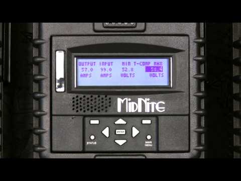
runs through the Aux menu options.
Last edited by karrak; 05-22-2017, 08:33 AM.Off-Grid LFP(LiFePO4) system since April 2013Comment
-
Cheese-n-Rice I cannot believe you are that ignorant to say something so STUPID. LFP cell charge discharge are extremely flat, and a difference of .16 volts is in excess of 50% of the batteries capacity. Lastly any cell in Absorb phase the voltage does not change. If you are seeing that large of voltage difference in a top balanced system, your cells are shot. Hell even in a Bottom Balanced system they would be Toast.
MSEE, PEComment
-
Sun Eagle this is clearly PURE Chi-Com SPAM. Why leave it up and not ban the user?Originally posted by LightWeightPowerMSEE, PEComment
-
Nope, he's right. Charge curves of LiFePO4 are very flat - except near 100% charge and 100% discharge. That's why the voltages start to diverge so much as he approaches 100% SOC. Look at a .2C charge curve for a typical LiFePO4; a .16 volt difference might mean the difference between 25% and 75% of capacity , but also means the difference between 85% and 95% of capacity. That's because the curve isn't linear. Any difference in cell capacity is thus amplified at the extremes of charge - and where they are worst depends on whether you top or bottom balance.
The terms "bulk" "absorb" "float" have no meaning in LiFePO4 charging. There is constant current and constant voltage; that's it. When you get close to 100% charge you are going to see a lot more voltage difference than when you are at 50% charge, due to the nonlinear relationship between SOC and cell voltage.Lastly any cell in Absorb phase the voltage does not change. If you are seeing that large of voltage difference in a top balanced system, your cells are shot. Hell even in a Bottom Balanced system they would be Toast.
Comment
-
Hogwash Jeff. Gotta call BS. That is exactly what it is, Every Battery Charge made for Pb and Lithium is a very simple CC/CV charger. Absolutely no difference between them except voltage set points and how you terminate the charge.
CC = Constant Current = Bulk
CV = Constant Voltage = Absorb and FLOAT
Nothing more than gimmick marketing names. Just like Pb batteries, there are only 3 types of SLI, Hybrid, and Deep Cycle. Hybrid is the gimmick market like Golf Cart, RV. Marine, Trolling Motor, Leisure, Floor Machine, Traction, Stationary and the list goes on. So stop the BS I know better.
During CC aka Bulk phase, the charger pumps in a fixed constant amount of current until the battery voltage reaches the set point. Say 14.4 volts for example on either Pb or LiFeP04
When the battery voltage reaches set point begins the CV stage in which nothing really happens electronically except that the battery voltage has reached a point to about equal of the charger voltage set point and the Charger holds 14.4 volts. As either battery saturates, aka Absorbs, charge current tapers off toward 0 amps. Both a Lithium battery and FLA are fully charged to 100% when charge current tapers to 3 to 5% of C.
The only difference is Termination. Typically a FLA charger if it has the 3rd stage will lower the set point voltage to 13.2 to 13.8 volts called a Float Charge which is a gimmick term for Constant Voltage. Typically for a Lithium Battery you terminate the charge, but not necessary because they can Floated just like a Pb by lowering the voltage to 13.4 to 13.6 volts. Absolutely no difference and completely compatible. You just tweak the voltage set points
In fact on a solar system you want to Float Charge a Lithium Battery and Never Ever Fully charge them staying away from the knees at either end of the charge/discharge curve. Many charge controllers can be set up to do this simply by setting Bulk = Absorb = Float = 13.4 to 13.6 volts. Multiply by 2 or 4 for 24 or 48 volt systems. Works great. Follow that up by setting your LVD to 12, 24, 0r 48 volts and you eliminate the knee at the discharge side which you want to avoid like the plague. There should never be be more than .1 volt spread at any point except at the extreme edges of the charge discharge cure which you want to stay far away from.
You can say what you want about Bulk, Absorb, and Float, they are just marketing gimmick names made up, but fact is any charger is a CC/CV charger no matter how you want to spin it. Bulk is CC, and Absorb/Float is CV period end of story. Designed and built to many of them to count. Today you can buy a hobby charger made for RC freaks like myself. They can charge any battery types made today and all in the future for one simple fact. EVERY CHARGER IS CC/CV. The Hobby Chargers trick is the processor built inside so you can set the voltage, current limits, current cut-off to anything you want. Just about everyone of them has an A123 Systems setting. It is exactly the same algorithm used for PB a standard 3-Stage Bulk > Absorb Float, On a 4S LFP 14.4 until current reaches 3% of C and Floats at 13.4 volts. Exactly what A123 Systems says to do for their batteries.
So I am calling BS on you.
Read Battery Tender 5-stage LFP Charger.Click on Algorithms Fundamentals and learn.
Stage 1 Qualification Charge: checks to determine if it is safe to charge or not.
Stage 2 Recovery Mode: If 12 volt battery is greater than 4 volts or less than 8 volts, trickle current is applied for up to 4 hours. If greater than 8 goes to BULK
Stage 3 Bulk Charge: Constant Current to Set Point which begins Absorb stage.
Stage 4 Absorb: Constant Voltage until current tapers to predetermined level then goes to stage 5
Stage 5 Float: Constant voltage until the cows come home or you turn it off.
Read it for yourself and argue with yourself. When you get tired of that go read Battery University. If you really want to dig deep into every kind of battery I suggest you purchase the Battery Bible and learn something. The book title is Linden's Handbook of Batteries, 4th Addition. I will make it real easy for you and you can thank me later because you can download the 3rd addition for free here. Dave Linden and I worked on IEEE Battery Committee for 8 years and wrote the standards and practices still used today with a few dozen other pros. Be sure to read all 1500 pages. Way more than you have ever done for me.
Karrak is a fraud and dangerous, and you know it. He has been banned two times for dangerous and fraudulent post. He came here for one purpose to his own admission, to only harass me. Back at him, the SOB got exactly what he asked and begged for.Last edited by Sunking; 05-23-2017, 09:15 PM.MSEE, PEComment
-
Yes. That's what I just said.
Data talks, bull**** walks. You may hate his guts but he has the data to back up his assertions.Karrak is a fraud and dangerous, and you know it. He has been banned two times for dangerous and fraudulent post. He came here for one purpose to his own admission, to only harass me. Back at him, the SOB got exactly what he asked and begged for.
Comment
 Tweet
Tweet


Working...
😀
😂
🥰
😘
🤢
😎
😞
😡
👍
👎
☕
Comment