Announcement

Collapse
No announcement yet.

Where to Locate one odd cable in dual parallel bank

Collapse
X
 
  • Filter
  • Time
  • Show
Clear All
new posts

  • Where to Locate one odd cable in dual parallel bank

    Thanks in advance to on topic, thoughtful replies!

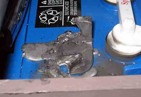
    I have a 48V AGM battery bank comprised of 8, 12V "Energy Power" (Vision brand) EV8D batts. The batts are wired as dual parallel strings of 4. During installation, one of the 4/0 battery cable terminal ends got damaged from an arc. I'm trying to figure out if there is a "best location" to put this particular cable in the bank. It made sense to me that it might be best to install this cable as one of the string interconnecting cables, rather than as a string "intra"connecting cable, to keep the resistance of each strings relatively the same.
    Thoughts?
    battery layout.pngdamaged cable.jpg

  • #2
    Toss all those cables. They look like they were crimped with a hammer & nail, and are a fire waiting to happen.
    I've never seen a crimp like that before on a high amp battery cable, and I would never trust them.
    -edit-
    Sorry, that sounds really harsh, but I believe it to be truth, AFIK, good cable crimps are 6 sided and are about 3/4 of the entire socket
    Last edited by Mike90250; 05-19-2017, 01:32 AM.
    Powerfab top of pole PV mount (2) | Listeroid 6/1 w/st5 gen head | XW6048 inverter/chgr | Iota 48V/15A charger | Morningstar 60A MPPT | 48V, 800A NiFe Battery (in series)| 15, Evergreen 205w "12V" PV array on pole | Midnight ePanel | Grundfos 10 SO5-9 with 3 wire Franklin Electric motor (1/2hp 240V 1ph ) on a timer for 3 hr noontime run - Runs off PV ||
    || Midnight Classic 200 | 10, Evergreen 200w in a 160VOC array ||
    || VEC1093 12V Charger | Maha C401 aa/aaa Charger | SureSine | Sunsaver MPPT 15A

    solar: http://tinyurl.com/LMR-Solar
    gen: http://tinyurl.com/LMR-Lister

    Comment


    • #3
      1. To keep the two string resistances roughly equal, the resistance of the U-shaped black cable at the negative end should match the resistance (including contact resistances) of the U-shaped red cable at the positive end.
      You cannot use your salvaged bad cable anywhere in the diagram and not have it unbalance the two strings.
      Trying the find the "best" place for a bad cable is foolish.

      2. I concur with Mike's advice to replace all of your cables or have new connectors properly crimped onto them if there is enough wire length.

      SunnyBoy 3000 US, 18 BP Solar 175B panels.

      Comment


      • #4
        Originally posted by Mike90250 View Post
        Toss all those cables. They look like they were crimped with a hammer & nail, and are a fire waiting to happen.
        I've never seen a crimp like that before on a high amp battery cable, and I would never trust them.
        -edit-
        Sorry, that sounds really harsh, but I believe it to be truth, AFIK, good cable crimps are 6 sided and are about 3/4 of the entire socket
        Sounds like Sunking advice.

        Comment


        • #5
          Originally posted by Laspher View Post

          Sounds like Sunking advice.
          Or the OP can keep them poorly crimped wires and light up a cigarette around a gas can. Stupid is as stupid does.

          Comment


          • #6
            Originally posted by Laspher View Post
            Sounds like Sunking advice.
            No, it is not. I did not disparage anyone, or say you are a Fool (that's a Mr T thing) or rant insults. It's no skin off my hide if the OP enjoys the roulette wheel of Fire or Battery Replacement.

            Powerfab top of pole PV mount (2) | Listeroid 6/1 w/st5 gen head | XW6048 inverter/chgr | Iota 48V/15A charger | Morningstar 60A MPPT | 48V, 800A NiFe Battery (in series)| 15, Evergreen 205w "12V" PV array on pole | Midnight ePanel | Grundfos 10 SO5-9 with 3 wire Franklin Electric motor (1/2hp 240V 1ph ) on a timer for 3 hr noontime run - Runs off PV ||
            || Midnight Classic 200 | 10, Evergreen 200w in a 160VOC array ||
            || VEC1093 12V Charger | Maha C401 aa/aaa Charger | SureSine | Sunsaver MPPT 15A

            solar: http://tinyurl.com/LMR-Solar
            gen: http://tinyurl.com/LMR-Lister

            Comment


            • #7
              Looks like a drunk Indian made those crimps. I can say that because I am an Indian. They cal me FBI (Fricking Big Indian). Only close friends are allowed to call me FBI. Foe gets booty kicked if they call me FBI.

              Seriously those crimps will fail, most likely the first time you put a heavy current demand on them. Here is your future. Melted battery post and wire terminal. You also get a bonus prize, a nice little fire to deal with.


              Here is what a proper termination looks like. See two very nice hexagon temps with proper die codes stamped by the crimper dies.


              Last edited by Sunking; 05-20-2017, 05:49 PM.
              MSEE, PE

              Comment


              • #8
                Originally posted by Sunking View Post
                Looks like a drunk Indian made those crimps. I can say that because I am an Indian. They cal me FBI (Fricking Big Indian). Only close friends are allowed to call me FBI. Foe gets booty kicked if they call me FBI.

                Seriously those crimps will fail, most likely the first time you put a heavy current demand on them. Here is your future. Melted battery post and wire terminal. You also get a bonus prize, a nice little fire to deal with.


                Here is what a proper termination looks like. See two very nice hexagon temps with proper die codes stamped by the crimper dies.

                Actually if his copper tube homemade terminals are soldered and yours are crimped, he has a better connection between his wire and connector and probably has less chance of a fire than yours...... assuming yours are not soldered but I am sure they are.

                Comment


                • #9
                  Originally posted by 685eric View Post

                  Actually if his copper tube homemade terminals are soldered and yours are crimped, he has a better connection between his wire and connector and probably has less chance of a fire than yours...... assuming yours are not soldered but I am sure they are.
                  Sorry but you are wrong here. Properly crimped lugs are crimped with such high pressure that the strands and lug fuse together. If , in the case of a high resistance connection such as a loose connection the lug can heat up to the point that the solder will liquefy and flow out of the connection similar to the melted stuff you see in the pictures. Solder is not recommended in these type connections but if it is done it should be done after properly crimping.
                  2.2kw Suntech mono, Classic 200, NEW Trace SW4024

                  Comment


                  • #10
                    Simple answer for high current terminations. DO NOT SOLDER THEM. The heat generated from the high current will melt the solder and loosen the connection.

                    Solder is for low temperature applications because of its low melt point to make it flow to the wire connection. That is why it is used on PC boards or low current electrical connections. If it is easy to melt the solder to make the connection then it is easy to melt the solder to open the connection and cause a problem.

                    Comment


                    • #11
                      Solder is not as good a conductor as copper. It does fine for minimal power communications circuits,
                      bonding and keeping moisture out. If it is relied on in very low impedance (battery) circuits, you may
                      get into trouble. Bruce Roe

                      Comment


                      • #12
                        Originally posted by bcroe View Post
                        Solder is not as good a conductor as copper. It does fine for minimal power communications circuits,
                        bonding and keeping moisture out. If it is relied on in very low impedance (battery) circuits, you may
                        get into trouble. Bruce Roe
                        But it still has a lot lower electrical (and thermal) resistance than a poorly done and poorly understood crimp, and a lot less resistance than a simple clamp. As a practical matter, for large current carrying applications, a well designed and subsequently well executed crimp is usually the connection of choice., which can have about the same or perhaps less electrical resistance than a soldered connection as well as the practical and safety imperative mechanical and strength advantages with respect to durability. Soldered joints are better for small current carrying joints that will not be subject to much, if any movement, mechanical stress or vibration.

                        Comment


                        • #13
                          Well I soldered my cables. I don't plan on having a large enough current to melt the solder....

                          Comment


                          • #14
                            Originally posted by 685eric View Post
                            Well I soldered my cables. I don't plan on having a large enough current to melt the solder....
                            Any chance anything can move ?

                            Comment


                            • #15
                              Originally posted by 685eric View Post
                              Well I soldered my cables. I don't plan on having a large enough current to melt the solder....
                              This is one of the few posts that deserves whatever invective Sunking can provide.
                              CS6P-260P/SE3000 - http://tiny.cc/ed5ozx

                              Comment

                              Working...
                              X