Anderson are superior connectors to MC4 However you would not use PP connectors as they are not sealed. You want to use a 3 position mini PL PACK. You can even Select the Female to be panel mounted so you can mount it on the RV. Something like an Outdoor Receptacle. It will be Plug-N-Play. Do not use MC4.
On the exterior series connections, if i mount the panels on the roof, what is a more waterproof connector the mc4 the panels come with or an Anderson pp15?
Thanks
MC4 is great once the connection is made. Try not to leave the unconnected ends exposed though, short circuit them together if you aren't going to make the final connection soon. No reason to cut the MC4 off and invite problems by using something different.
On the exterior series connections, if i mount the panels on the roof, what is a more waterproof connector the mc4 the panels come with or an Anderson pp15?
So if I wanted to run a 25 foot "unmbilical" on my 12 Volt system, and put my 2 -260 watt panels on the ground in series (according to your chart above for 15A at 3% drop), I'd need to run a 8/2 SO cord? it would not be required to be fused unless I wanted to use the fuse as an on/off switch for the incomming curent, correct?
Now for the real answer.
The chart only applies to 12 volts fixed voltage. Your two panels in series is many times higher than 12 volts. I assume you have 60-cell panels? Correct? If correct with both wired in series is should be roughly 60 volts Vmp or 5 times higher than 12 volts. That means 5 times the distance. You really do not need to worry about Isc for voltage drop as it is not normal operating condition. Isc only has to do with making sure that you are using at least minimum size wire.14 AWG is minimum requirement in your application. NEC codes do not apply to RV and SO cord has higher temp (105 C) ratings. #14 AWG 2-conductor SO is rated at 18 amps continuous, and 12 AWG is rated @ 25 amps. So no issue with either cable type. Just use 2-conductor if you can find it. If 3 conductor, just do not use the Green Wire.
For voltage drop you use maximum load current and in your case is 15 to 16 amps. Armed with that knowledge then:
#14 AWG is good to 30 feet 1-way
#12 AWG is good for 50 feet 1-way.
# 10 AWG is good for 100 feet 1-way
#8 AWG is good for 200 feet 1-way
Much less expensive and much easier to work with. No fuses required.
So if I wanted to run a 25 foot "unmbilical" on my 12 Volt system, and put my 2 -260 watt panles on the ground in series (according to your chart above for 15A at 3% drop), I'd need to run 8/2 SO wire? and it would not be required to be fused unless I wanted to use the fuse as an on/off switch for the incomming curent, correct?
That chart isn't applicable to the PV side of the charge controller, only the 12 V circuits that are tied to the battery.
Your panels have something around 9 A short circuit current, and in series, will operate at around 60 V. Even 14 AWG would max out at around 2% drop, and 12/2 or 10/2 would be fine if you want to reduce the loss from there..
Yes, no fuses required on the PV circuit in that configuration.
So if I wanted to run a 25 foot "unmbilical" on my 12 Volt system, and put my 2 -260 watt panels on the ground in series (according to your chart above for 15A at 3% drop), I'd need to run a 8/2 SO cord?
And it would not be required to be fused unless I wanted to use the fuse as an on/off switch for the incomming curent, correct?
1) I was told a ANL fuse is a medium burn fuse and is recomended for this type of set up BUT it need to be with in 18" of the batteries. My problem is I can't mount that type of fuse within 18" of the batteries SO is it better to go with a MRBF terminal mounted right on the battery OR an ANL mounted 4 feet from the battery?
Pretty easy to answer with a question. What does the fuse protect?
Answer = Wiring. Nothing more, nothing less.
Batteries can deliver extremely high amounts of fault current. You want fuses at the SOURCE of Power. If you connect the fuse downstream you have left that section of wire unprotected between the source and fuse.
Originally posted by Carv
2) If I wire like the picture below with 2 main leads comming off the batteries to fuse/terminal distrabution blocks do I still need to fuse at the batteries or will they be protected by the fuse at the terminal block like shown below?
If I understand your question correctly, refer to answer 1
Originally posted by Carv
3) Is it better to run the charge controller like this where the battery charge fromt eh CC ties in to the incomming terminal side from the batteriesOR is it better to make separate runs back to the battery from the charge controller?
You wire the controller as shown in my diagrams fed from a fuse from the BATTERY Tern Post.
Originally posted by Carv
4) I noticed on Sun Kings suggested Diagrams that the Solar panels are not fused before the charge controller. I believe that it is required for the panels to be fused before the CC? And if I wire them in series do I need to fuse each panel or should I do like the above picture and fuse them both before the CC?
You would be wrong. Solar panels are current sources, not voltage sources. Look at a panels spec and note of Isc = Current Short Circuit = say 10 amps. Leave that panel shorted and it can never deliver more than 10 amps. You can run 10-amp on a 14 AWG wire 24 x 7 x 365.
Fuses are only required between the panels and Controller IF YOU USE MORE THAN 2 PARALLEL STRINGS OF PANELS. The whole point of using a MPPT Controller is so you can wire your panels in series so you do not have to use more than 2 parallel strings and have to use all that expensive combiners and fuses.
Originally posted by Carv
4-A) If I wire them in series how to I calculate the Amps required for a proper fuse? Is it total potential watts / volts = max possible amps?
If you were to use a fuse, it is the Panel Isc x 1.25. So if Isc = 10 amps x 1.25 = 12.5 amps. That would require a minimum 15 amp fuse and 14 AWG wire, you can run 12.5 amps 24 x 7 x 365 days and never heat up the wire. No need for the fuse, nor is it required. You can use it if you want, just no requirement for them.
What you are missing is the BATTERIES are the POWER SOURCE, not the panels. The Batteries are the only thing that can deliver enough current to burn things up. So look at my drawings agina and you should get the point. There is a fuse going to the CC with a 10 AWG wire and 60 amp fuse. There is another fuse going to the loads Drawing 1 is 100 amp fuse with 4 AWG wire, and drawing 2 is 150 amp fuse protecting the 2 AWG wire.
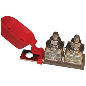
The Fuse protects the wiring. Nothing more, nothing less. A Blue Sea 2151 Dual Battery Fuse Block makes life very easy and safe. Bolt it directly to the Battery Term Post and you are good to go. One fuse to the Charge Controller, and one fuse to the Load. As in my drawing a 10 amp to CC, and either 100 or 150 in the other. Simple..
In low voltage systems you design for Voltage drop. Use this chart 3% columb for fuse and distance. Example if you have a 100 Amp Fuse and the 1-way distance is 20 feet you would need 2 AWG wire. Simple.
Note this chart is based on 12 volt battery systems. At 24 volts double the distances. 48 volt quadruple the distances
As to #4 You only need to fuse each panel/string of panels when you have 3 or more in parallel . The amperage of any string is the amperage of the individual panels in that string. Your panels have an Imp of about 8.5 amps and a series fuse rating of 15 amps. The only pic I could find is for a Yingli 255 watt panel. Hence my guess of about 8.5 amps.
I Picked up 2 brand new Yingli 260 watt 60 cell grid tie panels for a smoking deal of $100 each from a member here, thank you Mike! (If you're looking for panels he has more 310-988-9711)
Now I need to buy my fuses and have questions:
1) I was told a ANL fuse is a medium burn fuse and is recomended for this type of set up BUT it need to be with in 18" of the batteries. My problem is I can't mount that type of fuse within 18" of the batteries SO is it better to go with a MRBF terminal mounted right on the battery OR an ANL mounted 4 feet from the battery?
2) If I wire like the picture below with 2 main leads comming off the batteries to fuse/terminal distrabution blocks do I still need to fuse at the batteries or will they be protected by the fuse at the terminal block like shown below?
3) Is it better to run the charge controller like this where the battery charge fromt eh CC ties in to the incomming terminal side from the batteriesOR is it better to make separate runs back to the battery from the charge controller?
4) I noticed on Sun Kings suggested Diagrams that the Solar panels are not fused before the charge controller. I believe that it is required for the panels to be fused before the CC? And if I wire them in series do I need to fuse each panel or should I do like the above picture and fuse them both before the CC?
4-A) If I wire them in series how to I calculate the Amps required for a proper fuse? Is it total potential watts / volts = max possible amps?
You only need to fuse the panels or panel strings if you have more than 2 in parallel. If you only have two panels or if you have them all wired in series there is no requirement for fusing between the panels and CC.
I Picked up 2 brand new Yingli 260 watt 60 cell grid tie panels for a smoking deal of $100 each from a member here, thank you Mike! (If you're looking for panels he has more 310-988-9711) 20170713_170035.jpg
Now I need to buy my fuses and have questions:
1) I was told a ANL fuse is a medium burn fuse and is recomended for this type of set up BUT it need to be with in 18" of the batteries. My problem is I can't mount that type of fuse within 18" of the batteries SO is it better to go with a MRBF terminal mounted right on the battery OR an ANL mounted 4 feet from the battery?
2) If I wire like the picture below with 2 main leads comming off the batteries to fuse/terminal distrabution blocks do I still need to fuse at the batteries or will they be protected by the fuse at the terminal block like shown below?
3) Is it better to run the charge controller like this where the battery charge fromt eh CC ties in to the incomming terminal side from the batteriesOR is it better to make separate runs back to the battery from the charge controller? Copy of Handy Bob -Solar Wiring Set Up -Occasional Use Trailer.jpg
4) I noticed on Sun Kings suggested Diagrams that the Solar panels are not fused before the charge controller. I believe that it is required for the panels to be fused before the CC? And if I wire them in series do I need to fuse each panel or should I do like the above picture and fuse them both before the CC?
4-A) If I wire them in series how to I calculate the Amps required for a proper fuse? Is it total potential watts / volts = max possible amps?
The only sure way I know of to do that would be to install an additional thermostat that would switch the inverter from power save mode to normal mode whenever the refrigerator temperature rose above its set point. That would leave the refrigerator controls free to start the compressor normally and shut it off when its own cycle was complete. That would then let the inverter go back to sleep mode.
There may be other ways, such as powering the refrigerator electronics directly from battery DC, but any such attempt would require much more knowledge about the innards of the control circuit and a good amount of electronics expertise.
I was thinking the same thing BUT not sure how the temp controller sends the currant? I'm not sure if the digital thermostat just connects the power it's running off to rest of the circuit OR if it switches a seprate circuit (Yellow/Gray) and just uses Red/white to power itself? Can someone chime in confirm if a STC 1000 just acts as a switch and just puts the power through the circuit it's running off OR if it actually connects the power seprately from what it's running off of?
Based on how it's wired I think it might be the latter? (I marked the controller diagram as it was wrong from the factory).
If I went to a DC controller Could I put 115V AC through the Yellow/Gray port would be the question? If so then I could power the temp controller off DC and switch AC on/off to run the fridge and that would work and allow me to use sleep mode on the inverter.
Here's my currant wiring with my currant AC controller and original wiring diagram on the fridge:
Red AC positive
White AC Neutral
Grey? AC Neutral (Goes to motor)
Yellow -AC Positive
Black sheeth is temp probe
If I could make the power saving mode work I could run the fridge and it'd only consume 35 watts a day which would work. Here's the problem, on the power saving mode I can adjust the load sensing from 20W up to 115W to kick on BUT since I'm running a thermostat control on the fridge, there seems to be a "no power" loop using sleep mode where the fridge won't turn on and wake the inverter out of sleep mode. The fridge won't run and read the tempature since there is no power being sent to the thermostat. Since there is no power running the thermostat it fails to turn on the fridge AND therefore the inverter isn't brought out of sleep mode to send power to the fridge. Is there a way to make this work since the fridge and it's thermostat run off the inverter?
....
The only sure way I know of to do that would be to install an additional thermostat that would switch the inverter from power save mode to normal mode whenever the refrigerator temperature rose above its set point.
That would leave the refrigerator controls free to start the compressor normally and shut it off when its own cycle was complete. That would then let the inverter go back to sleep mode.
There may be other ways, such as powering the refrigerator electronics directly from battery DC, but any such attempt would require much more knowledge about the innards of the control circuit and a good amount of electronics expertise.
So other than electrical limitations & specs there is no real difference between 60 cell & 72 cell performance?
No real difference beyond the specs and physical envelope. 60 and 72 cell panels from the same manufacturer may be built with the same cells, the bigger panel just has more of them.


Leave a comment: