Tracer MPPT?

Collapse
X
 
  • Time
  • Show
Clear All
new posts
  • Brianinsocal
    Junior Member
    • Jun 2015
    • 31

    #1

    Tracer MPPT?

    MPPT TRACER 3215RN Solar Charge Controller 30A 12V 24V EP

    Anyone had experience with this MPPT charge controller? I will be running two Trojan t-105Re batteries with 3-100 watt 12v solar panels. This is the last thing I have to buy so I can finally get started.

    Any help is mighty appreciated.

    Thanks
  • Brianinsocal
    Junior Member
    • Jun 2015
    • 31

    #2
    MPPT TRACER 3215RN Solar Charge Controller 30A 12V 24V EP

    It says it has PWM output. What does that mean? Is that good?


    Thanks

    Comment

    • paulcheung
      Solar Fanatic
      • Jul 2013
      • 965

      #3
      I has the 40 amps version, it works good except it don't have the features that the expensive CC has. I.E. adjustable absorb voltage and preventive EQ charge, Also it don't has the detail log for power produced for the day etc. It is MPPT and will work the basic charge, T105RE is capable PSOC. this charger will be fine with them. I would get the 40 amps version to get a little room and their price is not much different.

      Comment

      • Raul
        Solar Fanatic
        • May 2015
        • 258

        #4
        I had the one you mention in your first post, my first Mppt. Not the best for the money and does get hot.
        I wonder why you guys don't go for the marine aplications CC since US has a larger market for it and better prices than Europe . I can even buy from US pay postage and still come out cheaper than buying from here.
        Marine orientated CC are robust and good underrated quality.

        Comment

        • Bucho
          Solar Fanatic
          • Dec 2013
          • 167

          #5
          Originally posted by paulcheung
          ...it works good except it don't have the features that the expensive CC has. I.E. adjustable absorb voltage...
          That is apparently not entirely true, check out this youtube about how you can use the remote meter to adjust the voltage: https://www.youtube.com/watch?v=lh9KPyUOiLg

          Comment

          • paulcheung
            Solar Fanatic
            • Jul 2013
            • 965

            #6
            Originally posted by Bucho
            That is apparently not entirely true, check out this youtube about how you can use the remote meter to adjust the voltage: https://www.youtube.com/watch?v=lh9KPyUOiLg
            I am talking about set the voltage to 15.5 volts and 16 volts to EQ from time to time. Tracer can't do that!. In order to fully charge my batteries I have to set the absorb voltage to 15.3 volts using my 675 watts panel to charge my 12 volts 450 AH bank. All the name brand CC can do it.

            Comment

            • Leehamrick
              Member
              • Mar 2013
              • 50

              #7
              I have two of the Tracer controllers and I have had no problems with them.
              I have seen them as high as 14.7 when I'm not using anything and it's a bright sunny day
              But soon as the sun goes down I show about 12.8

              I have been using them for about 3 years

              Comment

              • SunEagle
                Super Moderator
                • Oct 2012
                • 15161

                #8
                Originally posted by Leehamrick
                I have two of the Tracer controllers and I have had no problems with them.
                I have seen them as high as 14.7 when I'm not using anything and it's a bright sunny day
                But soon as the sun goes down I show about 12.8

                I have been using them for about 3 years
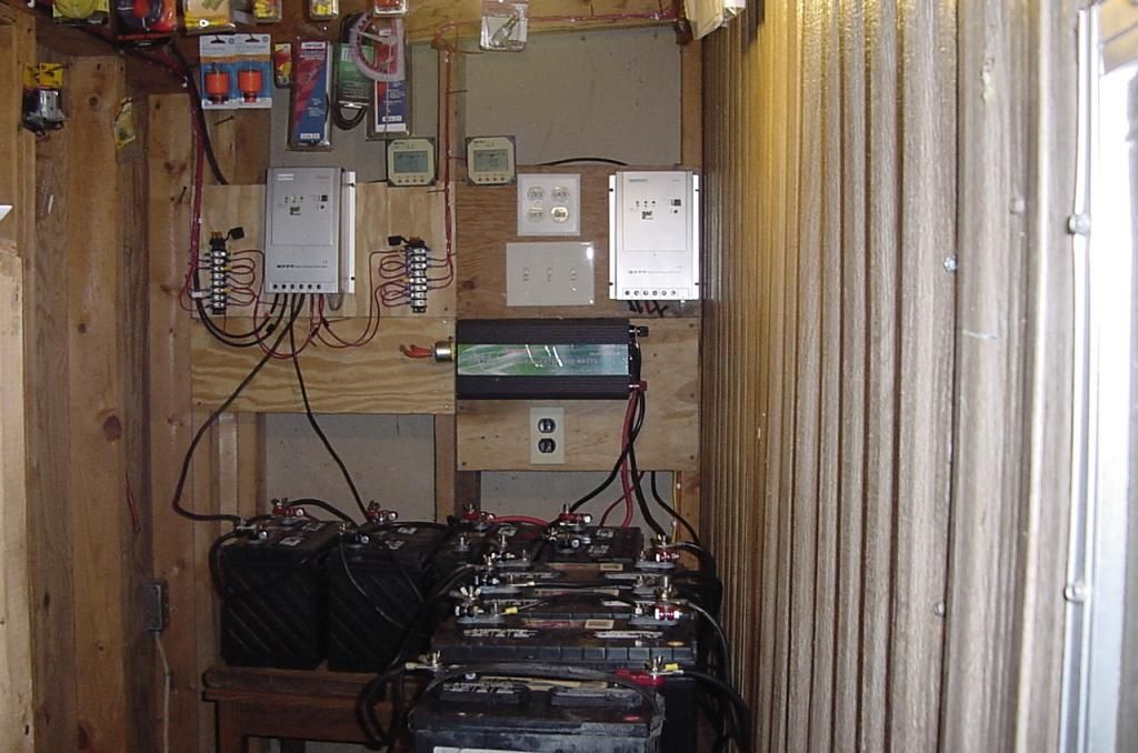
                I don't see any overcurrent protection between the Tracers and batteries or batteries and inverter. Looks a little dangerous to me.

                Comment

                • Silver_Is_Money
                  Solar Fanatic
                  • Aug 2014
                  • 148

                  #9
                  Originally posted by Leehamrick
                  I have two of the Tracer controllers and I have had no problems with them.
                  I have seen them as high as 14.7 when I'm not using anything and it's a bright sunny day
                  But soon as the sun goes down I show about 12.8

                  I have been using them for about 3 years
                  Are you running the two Tracers in parallel?

                  Comment

                  • jimindenver
                    Solar Fanatic
                    • Jun 2014
                    • 133

                    #10
                    All MPPT controllers use PWM to charge with. The MPPT part of it is a chip that decides how to best charge the battery when it isn't in absorb or float.

                    That Tracer model is a older model. They have a new line up this year.

                    Comment

                    • inetdog
                      Super Moderator
                      • May 2012
                      • 9909

                      #11
                      Originally posted by jimindenver
                      All MPPT controllers use PWM to charge with. The MPPT part of it is a chip that decides how to best charge the battery when it isn't in absorb or float.

                      That Tracer model is a older model. They have a new line up this year.
                      I think that you are over generalizing.
                      All MPPT controllers operate at other than the Maximum Power Point (MPP) when the battery cannot take the full output of the panel array without exceeding either the current or voltage limits of the battery.
                      But I have a hard time characterizing the output of a switching mode DC to DC converter as being PWM.
                      And when the panel power is less than its maximum (cloudy day or away from solar noon) the CC may still be operating at the MPP even though the CC is in Absorb or even Float mode.

                      The MPP tracking function requires that the input stage of the unit present a current drain on the panel which is not simply determined by the panel voltage and a fixed resistance. It also takes advantage of the excess voltage and converts it to additional current using a DC to DC converter.
                      One way to control the power going to the battery in Absorb or Float if it needs to be less than the full panel power at that moment is simply to adjust the operating point of the DC to DC converter away from the MPP. It does not, by any means, require changing over to a simple on-off series switching element in the way that a PWM controller always operates.

                      One way to tell whether the CC is behaving like a PWM CC is to look at the panel voltage at the input terminals when in Absorb or Float. If the voltage does not decrease to just a volt or two above the battery terminal voltage, then it is not operating in simple PWM mode.
                      SunnyBoy 3000 US, 18 BP Solar 175B panels.

                      Comment

                      • jflorey2
                        Solar Fanatic
                        • Aug 2015
                        • 2333

                        #12
                        Originally posted by jimindenver
                        All MPPT controllers use PWM to charge with. The MPPT part of it is a chip that decides how to best charge the battery when it isn't in absorb or float.
                        Not really. The term PWM refers to the OUTPUT of the charge controller. A PWM controller goes on and off, and that is seen at the batteries. An MPPT controller uses an internal high frequency DC-DC to provide a relatively smooth DC output, rather than the pulsating output that a PWM controller provides.

                        Many MPPT controllers use a method of PWM that is entirely INTERNAL - they use PWM (or another method, like phase-shift control) to drive the switch element of the DC/DC converter. Since it uses a DC/DC converter, the input can be a very different voltage than the output; this isn't possible with a PWM controller.

                        The "MPPT part" does not refer to the battery charge profile. It refers to "maximum power point tracking." This is a method whereby the DC/DC converter is adjusted so that the voltage at the input of the MPPT controller is at the solar array's maximum power point. There are several methods to accomplish this. This, again, is something that is not possible with a PWM controller, since it is only on or off.

                        The charge controller can implement the battery charging profile (float, absorb, equalize) as it sees fit. This is true of both MPPT and PWM controllers, with a level of sophistication that depends on their design.

                        Comment

                        • Roland Saul
                          Member
                          • Dec 2012
                          • 32

                          #13
                          I have the 20 amp version of that controller.

                          It seems to work ok, I am a total noob to this technology so I'll be as clear as I can.

                          This is my first setup, so I've taken it step by step with a lot of advice from the pros here.

                          I have 2 100 watt panels in series producing about 40 volts/10 amps max on the clearest of days at solar noon. This controller seems to actively track the panel voltage, amps, and gives an indication of battery condition. It takes the 40 volts down to anywhere between 13.5 - 14.2 for most of the charging cycle. This is the part for me where I suspect that this controller may be lacking, but I have no proof.

                          I charge 2 110 AH "marine" batteries, that appear to be in good condition. They are less than one year old, and have been totally discharged about 3 times, never left that way. I test them using the approved hydrometer, and the cells all appear in the healthy range. I believe I am testing using proper procedure. I have added a tiny bit of water to each cell over 1 year.

                          On to the battery condition display part of the controller. I am using the little remote display offered by Tracer.

                          With supposedly good batteries, and 220 amp hours of charge, I can use a 10 amp irrigation pump for 6 minutes, which should be equal to 1 amp hour if my math is right. At the end of that 6 minutes, the remote display will show my batteries at 50% SOC. If the panels are in full sun, that 60% will go to 90% in about 15 minutes or so. You would think that I am using a 2 amp hour battery.... But if I run the pump for half an hour, guess what? SOC = 50% If I run the pump for an hour and run 2 amps of lights for 2 hours, .... 50% I have edited the "battery type" field using the remote, and it shows my proper battery type and capacity. The controller seems to track charging voltage and amperage quite closely, but I am having BIG problems with the SOC readout. I never know what the real SOC is. I can only wait until I'm sure that my batteries are pooched, then I will briefly try this controller on a new set. I use about 10-12% of the optimal battery charge of my set, but this controller "says" I am using 50% . Further, It "says" that I am putting 50% of my charge back into 220 AH batteries in about one hour at 10 amps....... in full sun I can stand there and watch the numbers climb up to 90% where the charging amperage drops off...

                          My only conclusion is either that my one year old batteries have a combined capacity of only 12 amp hours, or that this controller is unable to accurately read the SOC of them. Not happy, but cannot prove until batteries are replaced. For what it's worth, I can run the pumps and lights for about 4 days/45 ish amp hours before my voltage at the battery terminals drops from 13.6 to 12.4 I hope this long-winded note helps somehow. Cheers

                          Comment

                          • inetdog
                            Super Moderator
                            • May 2012
                            • 9909

                            #14
                            Originally posted by Roland Saul
                            It seems to work ok, I am a total noob to this technology so I'll be as clear as I can.

                            This is my first setup, so I've taken it step by step with a lot of advice from the pros here.

                            I have 2 100 watt panels in series producing about 40 volts/10 amps max on the clearest of days at solar noon. This controller seems to actively track the panel voltage, amps, and gives an indication of battery condition. It takes the 40 volts down to anywhere between 13.5 - 14.2 for most of the charging cycle. This is the part for me where I suspect that this controller may be lacking, but I have no proof.

                            I charge 2 110 AH "marine" batteries, that appear to be in good condition. They are less than one year old, and have been totally discharged about 3 times, never left that way. I test them using the approved hydrometer, and the cells all appear in the healthy range. I believe I am testing using proper procedure. I have added a tiny bit of water to each cell over 1 year.

                            On to the battery condition display part of the controller. I am using the little remote display offered by Tracer.

                            With supposedly good batteries, and 220 amp hours of charge, I can use a 10 amp irrigation pump for 6 minutes, which should be equal to 1 amp hour if my math is right. At the end of that 6 minutes, the remote display will show my batteries at 50% SOC. If the panels are in full sun, that 60% will go to 90% in about 15 minutes or so. You would think that I am using a 2 amp hour battery.... But if I run the pump for half an hour, guess what? SOC = 50% If I run the pump for an hour and run 2 amps of lights for 2 hours, .... 50% I have edited the "battery type" field using the remote, and it shows my proper battery type and capacity. The controller seems to track charging voltage and amperage quite closely, but I am having BIG problems with the SOC readout. I never know what the real SOC is. I can only wait until I'm sure that my batteries are pooched, then I will briefly try this controller on a new set. I use about 10-12% of the optimal battery charge of my set, but this controller "says" I am using 50% . Further, It "says" that I am putting 50% of my charge back into 220 AH batteries in about one hour at 10 amps....... in full sun I can stand there and watch the numbers climb up to 90% where the charging amperage drops off...

                            My only conclusion is either that my one year old batteries have a combined capacity of only 12 amp hours, or that this controller is unable to accurately read the SOC of them. Not happy, but cannot prove until batteries are replaced. For what it's worth, I can run the pumps and lights for about 4 days/45 ish amp hours before my voltage at the battery terminals drops from 13.6 to 12.4 The 13.6 seems to be what my 110 volt charger used to leave the batteries at when I used it before I bought panels. I hope this long-winded note helps somehow. Cheers
                            Is your 10A irrigation pump a 12V unit? If not, then if it is most likely 120V AC, which using an inverter would amount to 10AH a 12V battery. Take another look at your results with this in mind, if that is your situation.

                            As for your battery condition, get a temperature compensated hydrometer and measure the specific gravity (SG) of the electrolyte to see what is actually going on.
                            Trying to estimate SOC based only on voltage is a losing proposition.
                            SunnyBoy 3000 US, 18 BP Solar 175B panels.

                            Comment

                            • PNjunction
                              Solar Fanatic
                              • Jul 2012
                              • 2179

                              #15
                              Originally posted by jflorey2
                              Not really. The term PWM refers to the OUTPUT of the charge controller. A PWM controller goes on and off, and that is seen at the batteries. An MPPT controller uses an internal high frequency DC-DC to provide a relatively smooth DC output, rather than the pulsating output that a PWM controller provides.
                              Not really, but generally ok.

                              The term PWM refers to a method of limiting the CV absorb-voltage to a set value, (high frequency switching done fast enough to emulate an inefficient linear device, but with much more efficiency). Both the inexpensive pwm cc and mppt cc use the pwm technique when reaching CV absorb to do this.

                              In the bulk, or CC stage, both pwm and mppt provide *smooth* dc, merely because the only thing that is happening is that the panel is merely directly connected to the battery. In an mppt controller, the dc-dc buck-boost just keeps the panel *voltage* higher, and thus pushes more current than a standard pwm controller which doesn't, and allows the low battery voltage to load or pull-down the panel voltage in this bulk stage.

                              Once you've reached absorb, it would be very hard to tell the difference between an inexpensive pwm controller and mppt controller - since BOTH use the pwm technique to limit the CV or constant voltage stage.

                              Just wanted to point this out that while yes, an mppt can be more efficient than a simple pwm controller, one has to watch out for marketing buzzwords and hype, like "smooth, full flavored dc" or some such blather.

                              Comment

                              Working...