 Tweet
Tweet
Thanks
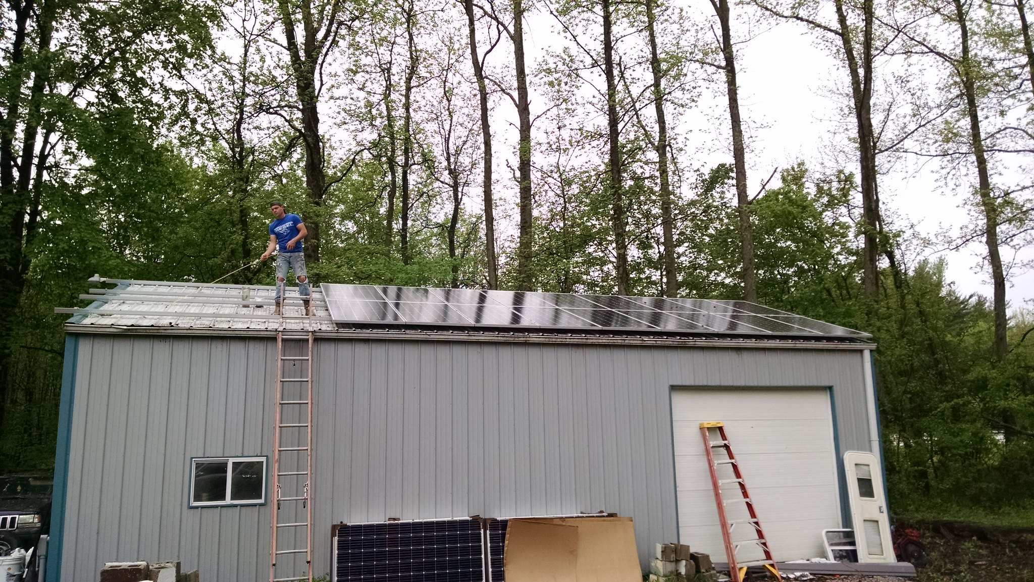
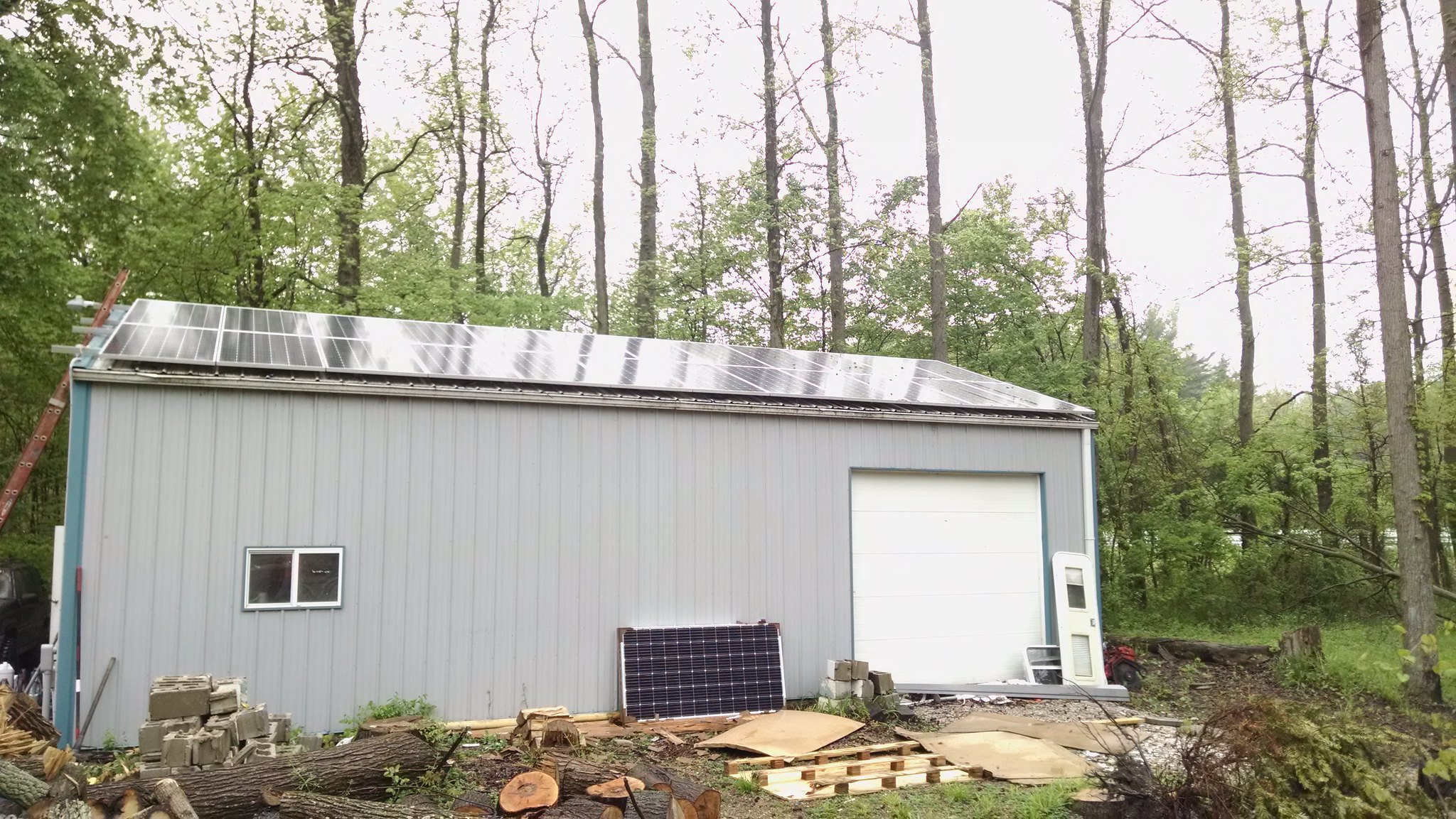
I'm good on everything other then the potential distance between the 2 rows... Is there any specs for that? I would think if the UFO clamp provides enough gap.. that as long as I maintained that spacing between the rows, it would be enough (which I'm over that a bit...)
I'm good on everything other then the potential distance between the 2 rows... Is there any specs for that? I would think if the UFO clamp provides enough gap.. that as long as I maintained that spacing between the rows, it would be enough (which I'm over that a bit...)


Comment