
 Tweet
Tweet
I have calculated that I would need 4 gauge wire between my (future) solar panel and a charge controller to account for a long distance. But when I look at various charge controllers, the terminals look like they would accept maybe 10 gauge or 8 gauge wire, but I can't see how 4 gauge would possibly fit. How would you make the connection to the controller with such large cables coming from a solar panel far away?
-
-
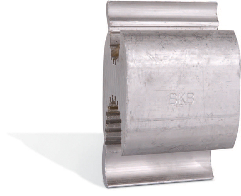
With "H" of "C" taps using a hydraulic compression tool. You do have the $2000 tool right.

 MSEE, PE
 -
Of course! Although I don't have this tool (nor will I likely be buying one), does it somehow put a connector on the end of a #4 wire that would fit in the smaller opening of a charge controller?
Comment
-
Look at the "H" TAPS. One side for a large wire, the other a smaller wire. That is how it is done.They wil run you about $20 for each tap and require tooling. The taps are solid plated copper and require a lot of pressure to compress.
Or they also make reducerrs you comprees on the end of the wire, but very bulking and clumsy.

Last edited by Sunking; 10-30-2017, 12:13 PM.MSEE, PEComment
-
You can install a fitting that will allow you to have one side big enough for a #4 Awg wire yet be small enough on the other side to fit a terminal connection for say a #8 awg wire.
The problem is getting enough pressure from a clamping tool to properly mold it around the #4 wire. Using a cheap tool will not get you what you want and the fitting could fail due to high resistance between the wire and it.
Maybe you can rent the hydraulic compression tool.Comment
-
Split bolt connectors are OK to transition from the #4 to something smaller, as well, no compression tool needed.
CS6P-260P/SE3000 - http://tiny.cc/ed5ozxComment
-
Thanks - I see now. But doesn't reducing down to (for example) a #8 wire now introduce a portion of the cable with higher resistance than the #4 wire? Would that present a safety issue if the current on the #4 wire is close to its rated ampacity, but higher than the #8 section now attached to it?Comment
-
CS6P-260P/SE3000 - http://tiny.cc/ed5ozxComment
-
Split bolt connectors are the preferred solution here. Cheap, compact, just a couple wrenches needed
to tighten them up. Double over that #8 if needed. I cover with plenty of tape, then add a wire tie so
the tape can't unwrap. And the most reliable for me. Bruce RoeComment
-
Thanks sensij. I didn't think about the short length and the fact that the wire size was truly just for the voltage drop, at least in terms of the wire coming from the PV panel, where the amperage should be less than 10A.
Speaking of amperage from the panel(s), is it correct to assume that you calculate the amps (Watts / Volts) coming from panels over those wires using the voltage that the panels actually put out at the beginning of the run (near the panel) -- that is, 17V-18V, correct?
Thanks again!Comment
-
Yeah, a 12 V panel on an mppt charge controller will be operating at something in the neighborhood of 17 V, and that is the voltage you would use for transmission loss calculations. For a variety of reasons, you'd probably be better off with a higher voltage solar panel, but it is hard to recommend one without (much) more information about the system you are designing and what you want it to do.CS6P-260P/SE3000 - http://tiny.cc/ed5ozxComment
-
Hi Sensij, This is really just for fun. Right now I've got a small 1000W inverter that I bought prior to Irma and used it when we lost power for 5 days. I have it connected to a 12V AGM battery and have a couple of dedicated outlets in the house connected to the inverter for easier access during another outage. Basically, we just want to be able to charge devices like phones/tablets/laptops and possibly watch some TV during an extended outlet. Maybe run a modem/router if that's not out at the same time. Not trying to run the refrigerator or A/C units or anything heavy like that. I'd probably just be hooking up a single 100W or 150W panel to recharge the battery during modest usage and keep it topped off in the meantime.Comment


Comment