X
 
  • Time
  • Show
Clear All
new posts
  • tyab
    Solar Fanatic
    • Sep 2016
    • 227

    NPFA 780 / LPI 175 Lightning Protection System for ground mounts

    (PART 1 of 5)

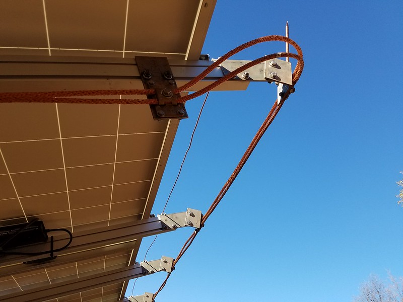
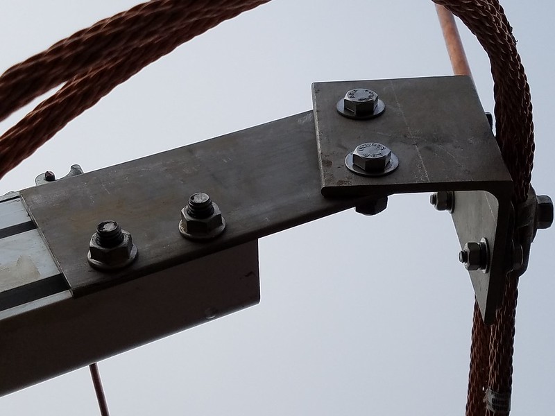
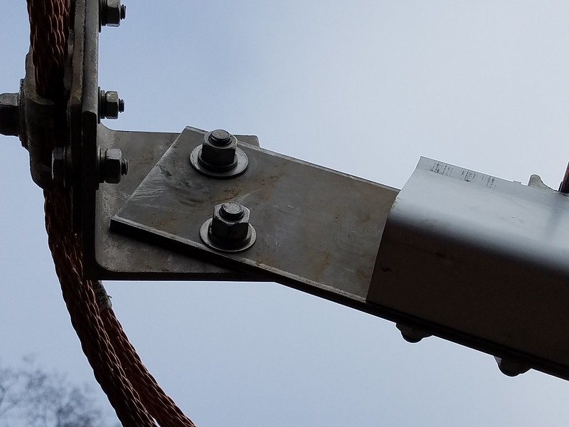
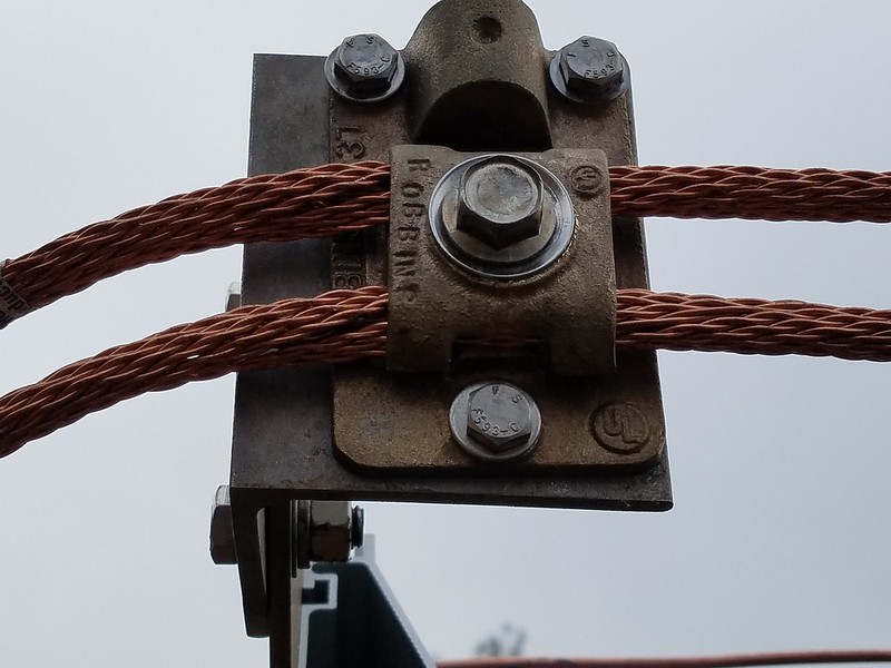
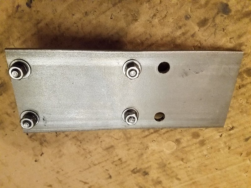
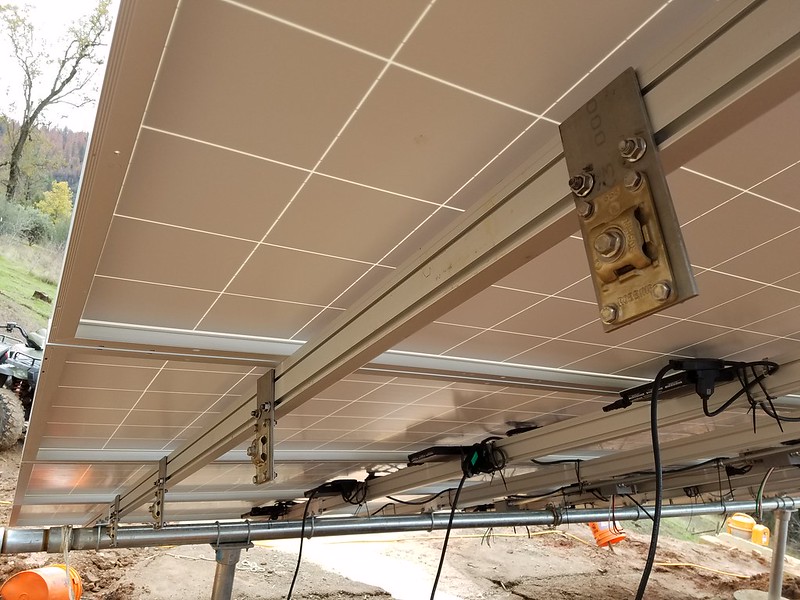
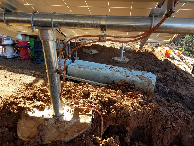
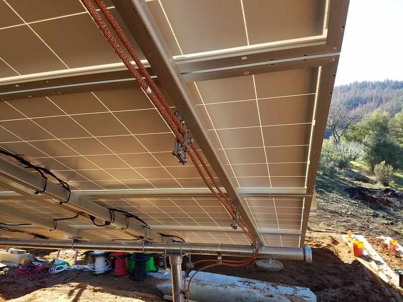
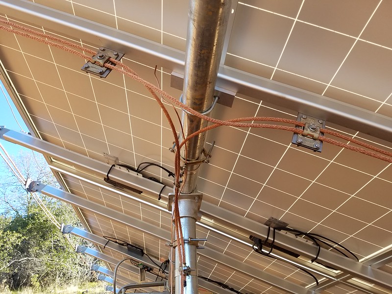
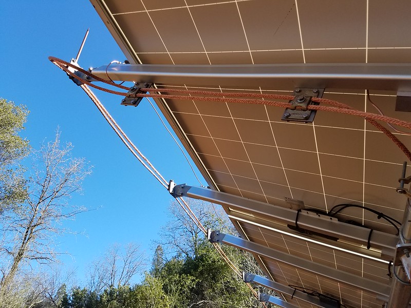
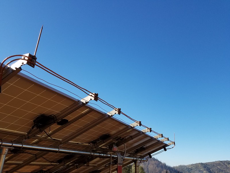
    This post is about the lightning protection system (LPS) I built for my ground mount solar system that has four ground mounts using the Iron Ridge XR1000 rail system and Robbinslightning components. All total the system has thirty-two XR1000 rails with 8 rails on each mount with a total of 80 260W panels and 80 Enphase microinverters.The result is a fully compliant NFPA 780 LPS that followed the additional guidelines in LPI 175.

    Note that I have not received any financial benefit from this work - nothing from either Robbinslightning nor Ironridge or any other company or business. All of this information is provided as-is and is my opinion only. My purpose in posting this is to show how I designed my LPS system and hopefully will be a starting guide to other DIY'ers.

    This post is mostly specific to ground mount solar systems. Rooftops solar systems have additional considerations for LPS not discussed here in that you are protecting the entire structure - not just the solar system.

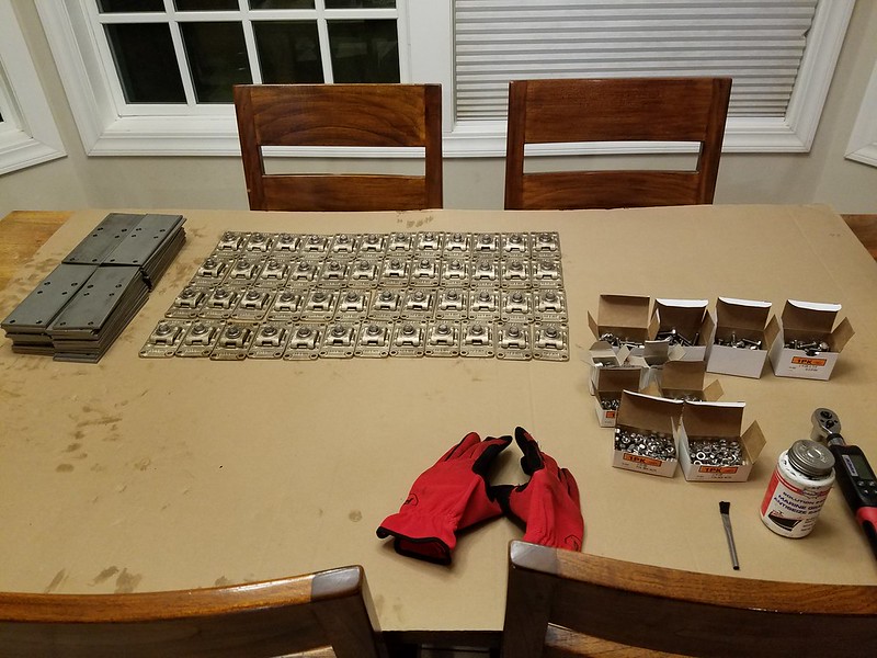
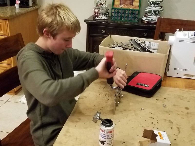
    This is a BBCode version of my Google Blogger post which I had to create by hand - cutting and pasting text and rebuilding image URL's. Images come from a public Flicr folder since Google Photos public URL's tend to have time limits. Time permitting I will try and keep this one up-to-date but the master document can be found at the blog site in my profile. Also note that forum software would not let me make this a single post thus I had to break it up into 4 posts due to the number of images.

    LPS are defined under NFPA 780 but additional information is from LPI 175. Both specs provide extensive additional information and are the best place to start if researching a LPS. From there one can find many research studies and not surprisingly the military has some of the best studies, an older unclassifed example is here: http://www.dtic.mil/dtic/tr/fulltext/u2/a261900.pdf

    NFPA 780 is organized in the the following sections.
    • 780.3 - Definitions.
    • 780.4.- The guts of the spec broken into many subsections.
    • 780.12 - Solar.
    • 780.A - Annex A explanatory material - a wonderful resource that answers "why".
    • 780.B - Annex B discusses the theory and physics of lightning protection.
    • 780.C - Annex C Explanation of the Bonding Principles.
    • 780.O - References - The definitive list of the body of work associated with LPS.
    The Light Protection Institute (LPI) 175 spec has similar sections with additional information.

    When starting off, I would recommend reading LPI 175 General section, then NPFA 780 Annex B and C, and then read 780.12 and then go dive into the extensive material in 780.4. When you get into the ground and bonding subsections, switch back over to LPI 175 and read the Grounding and Bonding sections.

    One thing that must be brought up is the cost-benefit of a LPS. 780 annex L is all about the risk assessment to understand both the actual risk and financial costs/benefit of a LPS. This includes possible insurance benefits or even requirements. For DIY'ers one may decide that a LPS provides additional personal time insurance against repairs that may be required in the future. My purpose is just to bring this topic up and individuals have to decide for themselves if the cost and time to install justify the possible reduced damage savings.

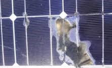
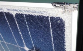
    There are two main risks to a ground solar system from lightning. First and least common is a direct hit or splash hit. This most likely will be catastrophic to a unprotected system - inverters blown due to internal shorting and panels made inoperative from either physical or electrical damage. From the studies I found, direct hits tend to cause damage to all panels in the array. This is a rare event but could result in extensive replacements. In addition, lightning can be castrostic to concrete - the large currents can vaporise the internal water and cause concrete to crack and even explode.

    http://www.solarpowerworldonline.com/2015/03/lightning-protection-for-solar-panels-protects-your-investment/

    http://www.30north.com.au/node/129

    http://www.30north.com.au/node/128


    I know the answer but want to know why. Table 310.104(A) lists USE as 75 deg C wet. There is no listing for SE cable But for more than one conductor you go to Art 338. 338.10(B)(4) refers to 334 except for 334.80 SE used at the 75 deg C rating? What about SER?


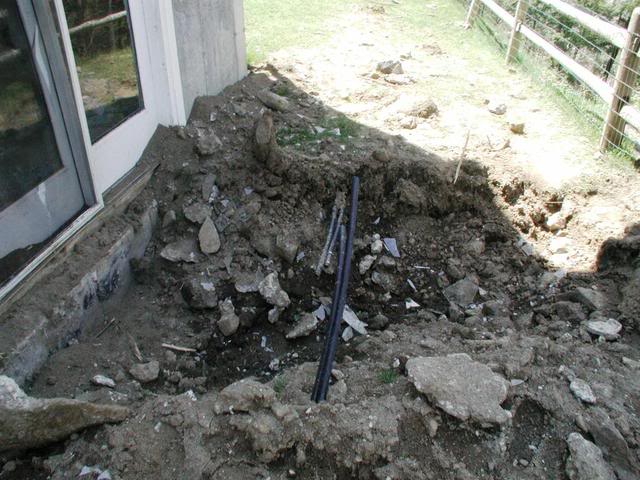
    Far more common is a near strike. This will cause a large voltage gradient in the soil and anything grounded will pick up that voltage gradient. This is what makes 690.47(D) so dangerous to a house - having multiple ground points with large voltage potential differences leads to side flashing and possible fires. For a ground mount, side flashing could wipe out panels (diodes) and inverters (shorting) and can even explode PVC boxes.

    This is all that is left of a PVC box on my front driveway electric gate from a lightning event a couple of years ago. Shorting inside the box heated the moist air causing it to explode - and is a good reason to not use any PVC above ground when possible.. This event also completely destroyed the gate controller box (PVC) and electronics - the parts of the cover were found 30' away, the gate motor fried, and exploded a 120v to 24v transformer in my pump house 80' away leaving nothing but small pieces of metal and plastic everywhere. It damaged the GFCI wall socket it was plugged into.


    There are many articles about partial damage from lightning. Not surprisingly, much of the research from this come from the insurance industry and of course the military. A lightning event happens and everything continues to work. Later the system fails. Was it due to partial surge from the prior lightning event? There are a number of research studies trying to quantify this but one runs into the issue of assigning the underlying cause.

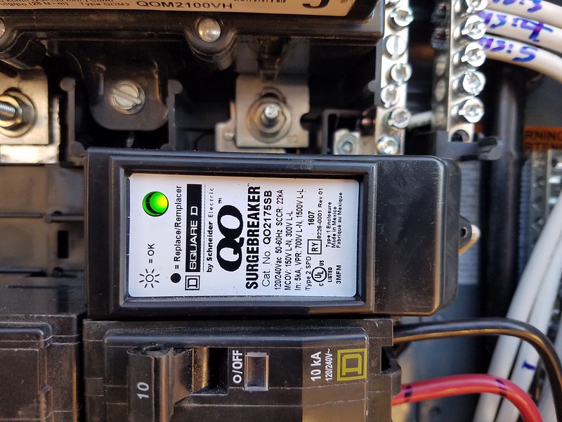
    The purpose of a lightning protection system for a ground mount has two major concerns - to protect against extensive damage from a direct hit and to protect against side flashing from voltage gradients. It is important to note that lightning is a chaotic event and LPS systems work on a probability - NFPA 780 claims that there is 98% probability of a direct hit being directed into the ground ring - but that means you have 2% chance of an event being completely uncontrolled and splashing anywhere and causing damage.

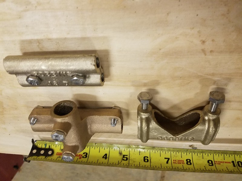
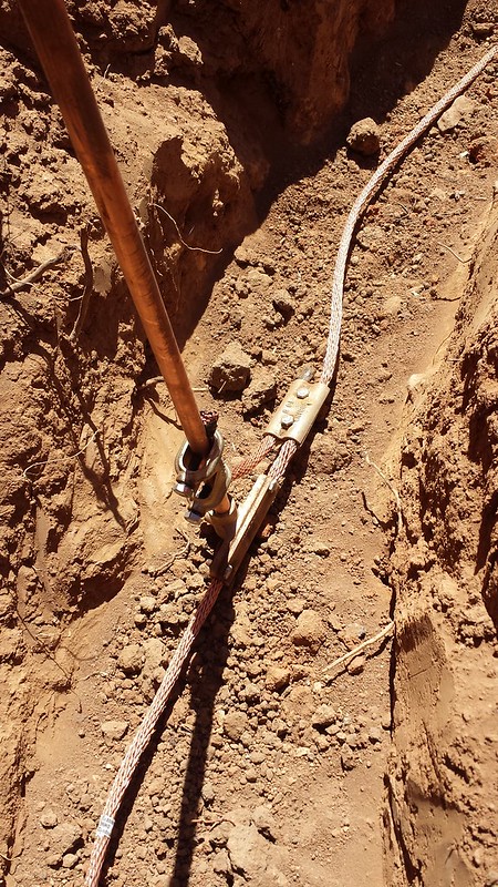
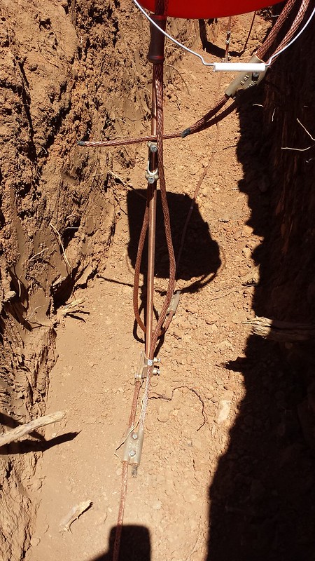
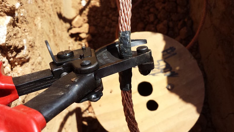
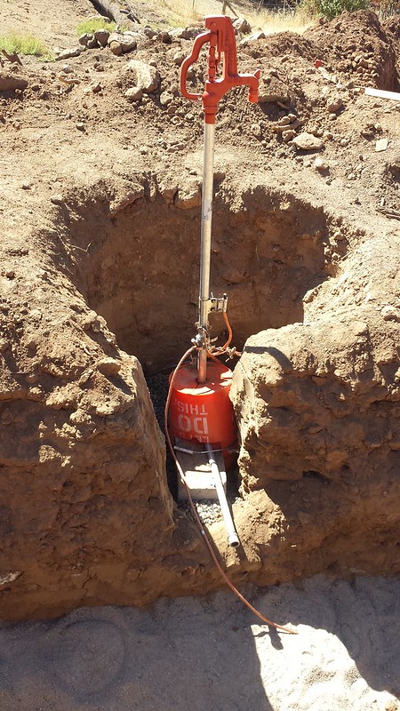
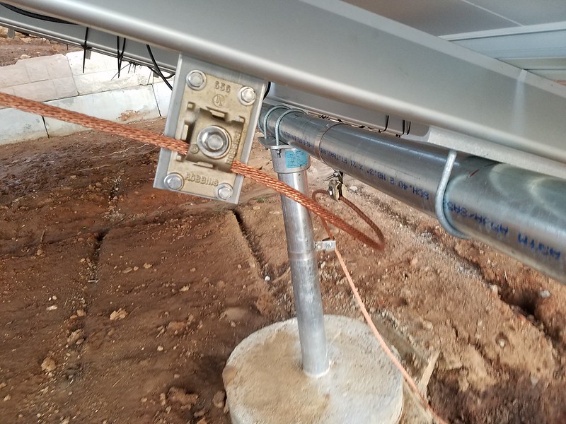
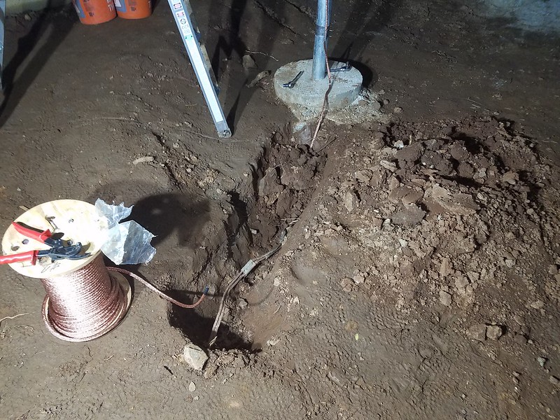
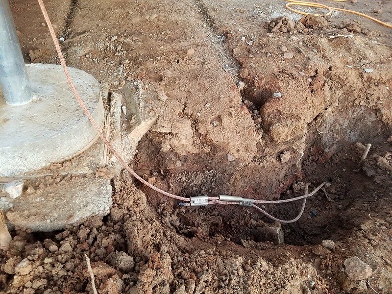
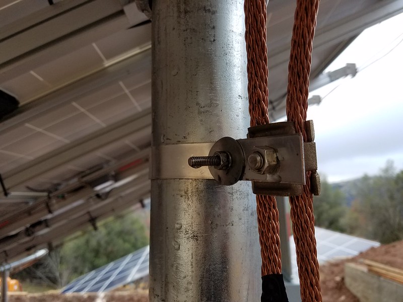
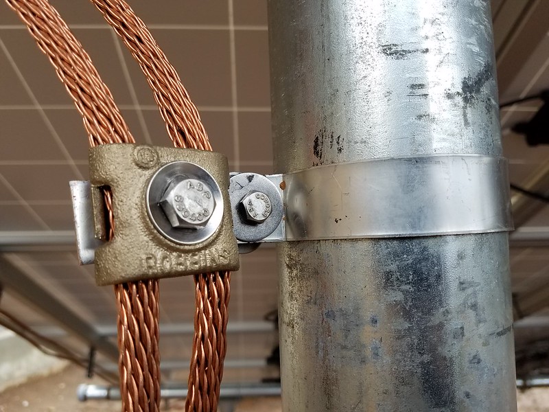
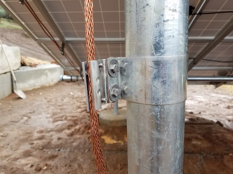
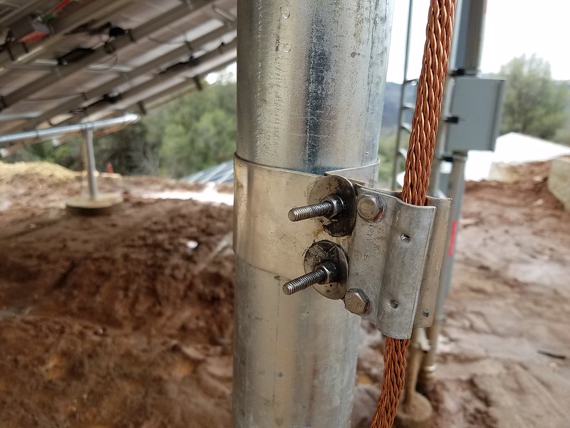
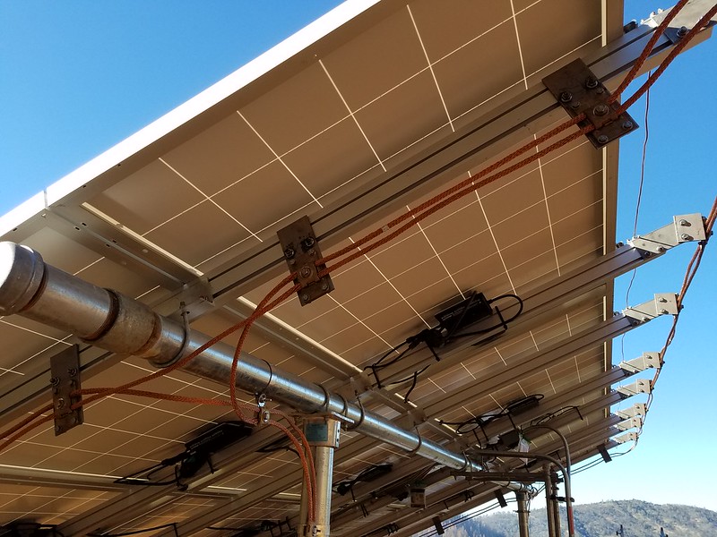
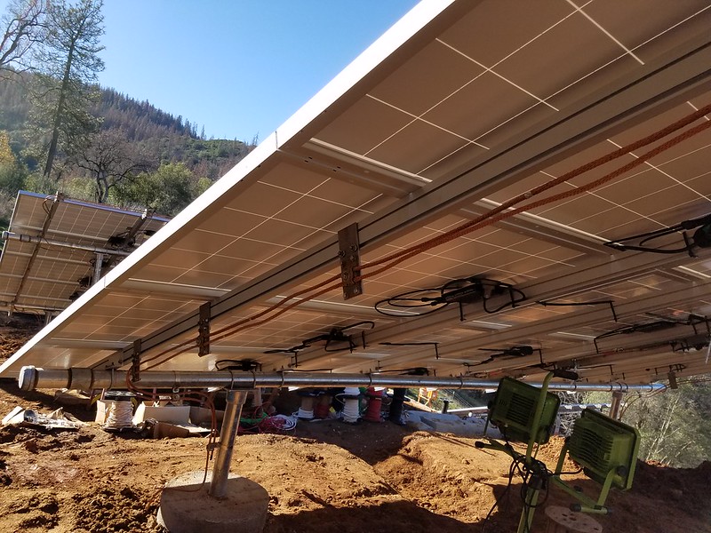
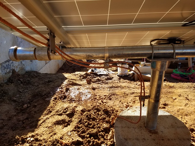
    Lightning protection systems for solar ground mounts comprise of three main parts.
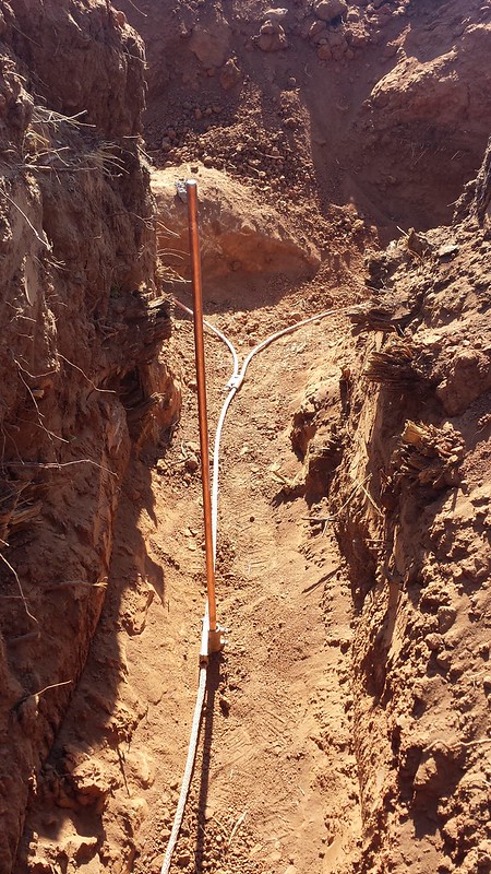
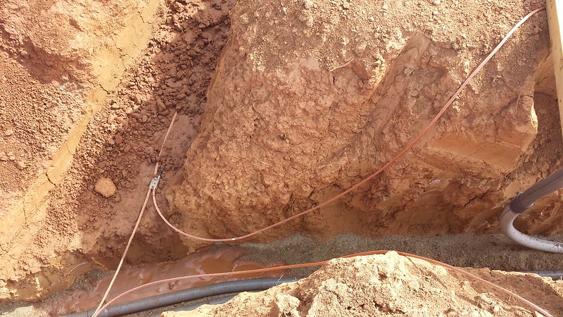
    • Ground Ring Electrode and below ground bounding.
    • Strike points, down conductors and above ground bonding.
    • Surge Protection.
    Last edited by tyab; 01-14-2017, 05:17 AM.
  • tyab
    Solar Fanatic
    • Sep 2016
    • 227

    #2
    (Part 2 of 5)

    Ground Ring Electrode system and below ground bonding

    780.12.5.1.1 requires a ground ring electrode made up of a class 1 conductor at least 18" underground that completely surrounds the entire solar system. It must bond any metallic structures coming out of the ground and must bond to all other nearby electrical systems.

    I installed my ground ring electrode during the summer when all trenches were wide open. Due to the dryness of our soil, 18" is not enough to hit permanently wet dirt, so all of my trenches are at least 3' deep. The purpose of the ground ring electrode system is to provide a equal voltage potential ring that is able to handle the currents the voltage gradient cause during a lightning event. All points of the ground ring will have mostly the same voltage at the same time no matter the voltage gradient of the surrounding soil.

    This is the oversized class 1 lightning conductor I used from robbinslighting, it is their cat 1 copper cable. Notice the basket weaving - this is to handle the pulse frequency of lightning with ramps from 0 volts to sometimes 100's of millions of volts in under 50 microseconds. And there are harmonics and even AC harmonics in the 100 MHz range that it also handles. Normal stranded cable has too much impedance at these pulse frequencies. After the initial spike DC pulse there is a long taper off with possible return strikes.


    Ground rods are optional for ground rings, but are a good idea for it gives your down conductors something strong to secure to close to the surface. Ground rods for lightning are normally 10' long but there are some exceptions in 780. Note that if you use ground rods with the ground ring, they must be UL 96 listed. This picture shows the difference between a UL 96 ground rod and one used for NEC 250 grounding, with the left one being Robbinslightning model 94-10. Notice the smoother copper coatings.


    All lightning splices are rated for underground and they are made of solid copper/bronze. Lightning does not require exothermic welding nor continuous runs - the splices are fully listed for grounding.
    Lightning splices are large and heavy compared to those used for NEC 250 type of bonding.

    Parallel splices and ground rod connections. The bottom left is a bus connect allowing a cable run to bond to a ground rod with no splices. The right one is a ground rod clamp, and the upper left is a parallel splice - allowing two cables to be bonded. Not shown is an inline splice (mine are all buried at the time I took this picture).


    This shows a parallel splice allowing another run to take off from an existing run. It also shows a bus type bond of a run to a ground rod without splices.


    To ensure life long bounding, in addition to the bus type bond above, every ground rod I installed has a parallel splice to a ground rod clamp.


    Ground clamps are over 3" long to connect the cable to a ground rod and have two bolts for compression of the class 1 conductor to the ground rod..

    LPI 175 recommends paralleled primary down conductors and this is what that looks like bonding to the UL 96 ground rod and ground ring electrode system. Here the ground ring has two parallel splices allowing dual bonds to come up from the ground ring. Both splices also bond to the ground rod using ground rod clamps giving secure support to the splices. The main ground ring is unspliced and bonded to the ground ring with a bus connector.


    Class 1 conductor is hard to cut, but if you use a good Klein cable cutter it is a one hand operation. You must tape that cut end or this stuff starts to unravel due to that basket weave.


    You must bond anything metallic coming out of the ground - that includes metallic water hydrants.


    The 1" pipe supporting the junction boxes are also bonded to the ground ring. These are the bonds that will attached to the 1" pipe. Parallel splices allow easy way to bond anything to the ground ring and provide a natural wide bend radius.


    All total I have 520' of class 1 cable at least 3' underground and another 90' of cable coming up waiting for bonds to the above ground part.

    All ground rods used for both 690.47(D) and 250.52/53 GEC are bonded to the ground ring electrode 3' underground.
    Last edited by tyab; 01-14-2017, 05:15 AM.

    Comment

    • tyab
      Solar Fanatic
      • Sep 2016
      • 227

      #3
      (Part 3 of 5)

      Strike points, bonds, and down conductors.

      The second part of the NFPA lightning protection system is the above ground strike points, down conductors, and bounding. This required me to design and build custom brackets - nothing existed that work with the Iron Ridge rail system. All of my brackets are made out of 3/16" thick x 3" wide plate stainless steel and the 90's are also 3/16" thick 3x3. This plate is hard to cut and drill so better use a band saw on the slowest speed with a bimetal blade and a drill press on the slowest speed with cutting oil.


      I have no idea on the total number of house I spent cutting and drilling them but it is extensive. Each hole is clamped and oiled during drilling. A total of 544 holes were drilled and I went through almost two bottles of the cutting oil for the entire project, three bi-metal band saw blades and two drill bits per size. The cutting oil is mandatory otherwise your bits will be destroyed in just a few holes.


      During a lightning event, the class 1 cable will be subject to forces of up to 200lbs applied in milliseconds as the cable tries to straighten out due somewhat to the massive electron flow but mostly the internal electromagnetic forces on the individual copper wires. The G forces are crazy high and one military study concluded that the forces can approach the shear strength of copper. Thus all lightning components above ground must be securely fasten to withstand these forces - solid metal brackets. This is why I chose to use stainless steel. My brackets will directly attach to the IronRidge rail via the 3/8" channel using stainless steel 3/8" hex nuts to handle those forces.

      Each mount needs the following:

      Rail end bracket - one per rail. In my case that is 8 thus a total of 32 of them. This consists of a 7-1/2" long bracket that connects to the rail for the last 3" of the rail and the last three inches of the bracket connect to the 3x3 90 cut 3.5" long. You drill both the 90 and rail end bracket to match your mount incline and I oversized those holes and used fender washers to allow field adjustment so they can be aligned exactly vertically. All of this hardware is 18-8 or 304 grade stainless steel and every bolt has it threads coated with anti-seize. My youngest son did a great job putting these together.


      On the end of the 90 you attach a listed lightning strike point - these also hold two parallel down conductors so only the ends will have actual strike points attached and the 6 middle ones will have a short 3/8" stainless hex bolt screwed into the strike point. These strike plates are held on by three 1/4" stainless steel hex bolts. The back of the strike plate is coated with copper anti-oxide (Peen Union #11C)


      Installed they look like this (far right, this is the East most one and has a 12" strike rod). Two 3/8" hex bolts attach to the lower channel of the Iron Ridge rail, and the 90 is attached by two more 3/8" hex bolts through the oversized holes so the 90 can be aligned to be vertical.


      Two 3/8" hex bolts slide into the XR1000 rail and hold the bracket. Two 3/8" hex bolts into oversized holes are drilled and adjusted to make the angle vertical.


      Use oversized fender washers on the oversized holes to tightly grip the angle once adjusted.


      Strike plate is attached with three 1/4" hex bolts. All hardware must be stainless steel and should have stainless anti-seize on the threads. These robbinslightning strike plates are model 637A.


      Each mounts needs 12 brackets to hold the down conductors, 6 on the West most rail and 6 on the East rail. For me I needed 48 of them.

      These are 7-1/2" long 3/16" thick by 3" stainless steel plate drilled for the 3/8" Iron Ridge rail and a lightning bonding place. Here are all 48 ready for assembly.


      Each bonding plate is attached with four 1/4" stainless hex bolts.


      Robbinslightning model 656N bonding plate is about 3-3/4" long and about 2-1/2" wide and holds two conductors in parallel.


      Every stainless steel bolt gets stainless anti-seize and is torqued to correct specs.


      Last edited by tyab; 01-14-2017, 05:19 AM.

      Comment

      • tyab
        Solar Fanatic
        • Sep 2016
        • 227

        #4
        (Part 4 of 5)

        Installed they look like this - install all to face outwards. Four of them are between the North and South horizontal pipe and two are north of the North pipe. Note that you had to put those 3/8" hex bolts in to the rail prior to installing the rail on the pipe so it required planning ahead.


        The ones on the West rail face the opposite direction - again outwards.


        Once all the brackets are installed, we again dug up the mud filled trenches that had the bonds to the ground ring electrode and started running wire.


        Here is an entire mount finished with all bonds, The end result is parallel down conductors, bonds tying the North and South horizontal pipes. and bonds around every Iron Ridge cap. Every vertical pipe has a bond that connects directly to the ground ring electrode system.

        For splicing I am using both an inline splice and a parallel splice around the inline splice.


        The brackets holding the cable to the 3" galvanized pipe are listed for lightning. They are field installed - they come flat and you drill and bend them for your pipe size. I drilled all of them prior to installation and included two different oversized stainless steel fender washers to ensure they have a tight grip on the pipe and they are secured with 1/4" stainless steel hex bolts squeezing them together. The straps are made of coated copper about 3/16" thick and are robbinslightning model 677D-4 and hold two conductor in parallel.


        On the North vertical pipes I only need a single conductor for the last two supports on each pipe so I use robbinslightning model 62-4. While they come pre-drilled, you have to drill them to to match your pipe so either enlarge the existing holes or make new ones. Like the other straps they are made of solid coated copper and I used large fender washers to ensure a tight fit.


        Last edited by tyab; 01-14-2017, 05:20 AM.

        Comment

        • tyab
          Solar Fanatic
          • Sep 2016
          • 227

          #5
          Part 5 of 5.
          Here is a complete setup starting from the South West short vertical pipe where the primary down conductor is attached to the ground ring.


          The conductor closest to the rail is a bond that connects across the end caps and ties the North and South horizontal bars together. The lower one is the primary down conductor. In this method the entire 3" schedule 40 frame is also a down conductor but we are not in any way relying on the part of the pipe in ground concrete to be part of the ground ring.


          Here you can see the bond at the North side. The bonding conductor ties the vertical pipe to the horizontal pipe to the rail and does the same on the South side. This is the West side, the East side is identical. Thus all parts of the 3" pipe are bonded in at least two locations to at least two other pipes creating a equipotential ring out of the entire frame. This ensures that all parts of the frame and the lightning conductors and ground ring are at the same voltage potential at all times - reducing the probability of any side flashing.


          That #6 bare wire for 690.47(D) looks small compared to the class 1 conductors.


          Notice that your bends for class 1 conductor are large and smooth. 8" minimum radius for bends - any tighter and LPI 175 says that lightning can side flash due to increased impedance from the bend.


          Here is the entire North side. The upper conductor is the primary down conductor - closest to the strike points. The lower conductor is the secondary down conductor. In addition the entire 3" pipe frame is an additional down conductor. The strike points are solid copper 12" long and 3/8" diameter. NFPA 780 wants a minimum of 10" and anything 24" or longer needs additional supports.


          East side bonding is identical to the West side.


          The East side is identical to the West side. Now the lower one is a secondary down conductor and the upper one is the East bond for the horizontal pipes - completing the ring of the 3" galvanized pipe.


          South East bonding and attaching to the ground ring.


          Finally all of those trenches can be buried.

          All total above ground I used 630' of class 1 conductor and I ran out of class one conductor for mount 4. Thus mount 4 only has a single down conductor (that meets NFPA 780 spec). I did order another 250' reel and will finish mount 4 up when it arrives. It will not affect the inspection since it meets requirements.

          Surge Protection.

          780.12.4.2 wants surge protection that meets 780.4.20 which is a type 2 surge protection, I'm using a Square D QO2175SB in my solar subpanel.

          Last edited by tyab; 01-17-2017, 02:33 AM.

          Comment

          • tyab
            Solar Fanatic
            • Sep 2016
            • 227

            #6
            (part 5 of 5 - placeholder, I thought I put this in already).

            Comment

            • Mike90250
              Moderator
              • May 2009
              • 16020

              #7
              WOW

              What a impressive project !
              Do you add copper sulfate crystals to the ring trench ? (plumbing root killer and ground enhancer)
              Are you in Florida, or the High Sierra, that you have a lot of lightning ?

              personally, I think I would go with a decoy Franklin rods and the "rolling sphere" zone of protection 50 feet away, rather that adding strike spikes to the PV array, which insures a hit inches from the panels - and are those micro inverters under there too ?

              Or maybe a central high point 10' north of the array (no shade issues) to not pull a strike onto the array.

              And instead of the ground braid conductor, I wonder about 1.5" copper plumbing pipe - something equivalent to the mass of copper in the braid, but made and sold by the millions of feet. Or does the braid provide a better mechanical resistance to "bounce" when a strike hits ?

              Powerfab top of pole PV mount (2) | Listeroid 6/1 w/st5 gen head | XW6048 inverter/chgr | Iota 48V/15A charger | Morningstar 60A MPPT | 48V, 800A NiFe Battery (in series)| 15, Evergreen 205w "12V" PV array on pole | Midnight ePanel | Grundfos 10 SO5-9 with 3 wire Franklin Electric motor (1/2hp 240V 1ph ) on a timer for 3 hr noontime run - Runs off PV ||
              || Midnight Classic 200 | 10, Evergreen 200w in a 160VOC array ||
              || VEC1093 12V Charger | Maha C401 aa/aaa Charger | SureSine | Sunsaver MPPT 15A

              solar: http://tinyurl.com/LMR-Solar
              gen: http://tinyurl.com/LMR-Lister

              Comment

              • ButchDeal
                Solar Fanatic
                • Apr 2014
                • 3802

                #8
                Originally posted by Mike90250
                WOW

                personally, I think I would go with a decoy Franklin rods and the "rolling sphere" zone of protection 50 feet away, rather that adding strike spikes to the PV array, which insures a hit inches from the panels - and are those micro inverters under there too ?
                Wouldn't the EMP from a strike so close fry the array ( modules, bypass diodes, and micros ). I have had a strike fry ever Ethernet connection on 50+ computers and ever switch port in use as well as many other devices. The strike was to the adjacent building. A similar thing happened at my home when a strike to a tree 40 feet in front of the house, caused several electronic devices to fail.
                OutBack FP1 w/ CS6P-250P http://bit.ly/1Sg5VNH

                Comment

                • Sunking
                  Solar Fanatic
                  • Feb 2010
                  • 23301

                  #9
                  Nothing can survive a direct strike or nearby if EMP is a concern. At least not at the consumer level. Polyphaser and a couple of manufactures make EMP arrestors, but only Cellular carries and military can afford them.
                  MSEE, PE

                  Comment

                  • DanS26
                    Solar Fanatic
                    • Dec 2011
                    • 966

                    #10
                    Some of us DIY'ers need to be low cost producers......I think a cost benefit analysis is needed before this becomes SOP. Not that I don't admire your efforts.....it seems overkill for the what you are trying to protect. In other words, you can buy a lot of spare parts in panels and inverters for that investment in copper braid, connections and stainless steel angle.

                    Not sure that all that copper and stainless steel will give you any more protection than all those UFER's setting under your arrays.

                    Loved the pic of the assembly line in kitchen/family room next to the sewing machine.....you are a true DIY'er.

                    Comment

                    • tyab
                      Solar Fanatic
                      • Sep 2016
                      • 227

                      #11
                      I'll try and answer comments below.

                      Do you add copper sulfate crystals to the ring trench ?
                      No I did not, at 3' depth the ground is permanently moist insanely hard to trench clay with endless granite rocks. I figured that was good enough In the pictures they look dried out since they were open all summer.
                      Are you in Florida, or the High Sierra, that you have a lot of lightning ?
                      No central California Sierra mountains about 20 miles from Yosemite southern entrance. We are at 3200' and get thunder storms that are typical for the Sierra mountains. An hour south in Fresno they rarely get any.
                      personally, I think I would go with a decoy Franklin rods and the "rolling sphere" zone of protection 50 feet away, rather that adding strike spikes to the PV array, which insures a hit inches from the panels - and are those micro inverters under there too ?
                      I considered the following:
                      780.4.6.4 Overhead Ground Wires. Found some examples of this for large commercial systems but the supports need to be engineered and I could not find any low cost supports for the overhead wire.
                      Tall aerials on the North side of mount 2 to protect mount 1 and 2 and another set North of mount 4 to protect mounts 3 and 4. But the size is where I ran into issues. The total distance from the south of mount 1 to the north of mount 2 is about 55' and lets say we start the arial 10' back from that'. Using the 2:1 allowed for multiple-level roofs the aerial tip would need to be 33' above the ground. I did not bother computing the rolling sphere distance but just napkin math seems it would be equal or taller than that. I simply had no interest in a tall tower and support wires.
                      Yes the system is all microinverters - 20 on each mount.
                      And instead of the ground braid conductor, I wonder about 1.5" copper plumbing pipe - something equivalent to the mass of copper in the braid, but made and sold by the millions of feet. Or does the braid provide a better mechanical resistance to "bounce" when a strike hits ?
                      I never thought about it, but lets go through the spec.780.12.5.1.1 wants a ground ring. 780.4.13.4 defines a ground ring to be main-size lightning conductor or a grounding conductor of equivalent or greater cross-sectional area. So it seems that 780.4.13.4.2 allows a grounding conductor as long as it has the right cross-sectional area and that would be from 780.4.1.1.1.1 at least 57,400 cir. mils of copper. The robbinslightning conductor I used is their cat 1 which is 65,500 cir. mils and retails for $1.74/ft with significant discounts as long as you have a contractor license (we used my friends). So as long as your thick copper pipe is less than that per ft it would be a savings. A quick check of home depot online shows 1" copper pipe at $3/ft so... Then you would have the issue of splicing to that pipe with listed pipe splices (robbinslightning has a good selection). Not sure if that hassle would be worth it. I have never worked with 1.5" copper pipe - I wonder how easy it is to bend and such. I personally don't know if the braided cable is better/worse than solid.

                      (more later)

                      Comment

                      • bcroe
                        Solar Fanatic
                        • Jan 2012
                        • 5198

                        #12
                        So now you will half want a strike, to see how well the magnificent system handles it? I believe the logic to the braid
                        (instead of a pipe) is to maximize the surface area, as fast rate-of-rise current won't penetrate much past the surface.
                        Same thing as radio.

                        I have read, that sharp points can flow quite a bit of current as voltages build up before a strike. This tends to discharge
                        or defuse the immediate area, to encourage the strike to happen elsewhere. Don't know how that fits into having a strike.

                        Working all that stainless steel is quite a project. I bought some special tooling to help deal with that for the stainless
                        exhausts I put on my cars. Bruce Roe

                        Comment

                        • Sunking
                          Solar Fanatic
                          • Feb 2010
                          • 23301

                          #13
                          You do know the concrete piers used to support the ground rack is a better earth ground than anything you can bury in the dirt right?

                          I know NFPA 780 pretty good, I was a co-author, and I am afraid you have misinterpreted most of the requirements and purpose.
                          Last edited by Sunking; 01-15-2017, 11:26 PM.
                          MSEE, PE

                          Comment

                          • Sunking
                            Solar Fanatic
                            • Feb 2010
                            • 23301

                            #14
                            Originally posted by Mike90250
                            And instead of the ground braid conductor, I wonder about 1.5" copper plumbing pipe - something equivalent to the mass of copper in the braid, but made and sold by the millions of feet. Or does the braid provide a better mechanical resistance to "bounce" when a strike hits ?
                            Mike braided rope conductor is used on Down Conductors and to bond air terminals and all metallic equipment frames pipe etc. together. It is used because of the massive amount of surface area it presents. Lightning is a high frequency and lightning current rides on the surface of conductors called "Skin Effect". Conductors in the dirt should be bare, tinned, solid or class B Stranded conductors. Best practice for bonding conductors in dirt is thermally welded together.
                            Last edited by Sunking; 01-15-2017, 11:48 PM.
                            MSEE, PE

                            Comment

                            • inetdog
                              Super Moderator
                              • May 2012
                              • 9909

                              #15
                              Just FYI, the reason for the 8" bend radius is not increased resistance, it is increased impedance, mainly in the form of inductance.
                              Lightning current (both direct and induced) is not anything like pure DC and has some very high frequency components.
                              SunnyBoy 3000 US, 18 BP Solar 175B panels.

                              Comment

                              Working...