X
 
  • Time
  • Show
Clear All
new posts
  • HX_Guy
    Solar Fanatic
    • Apr 2014
    • 1002

    Any issues with adding fuses to my DC Negative inside the combiner box?

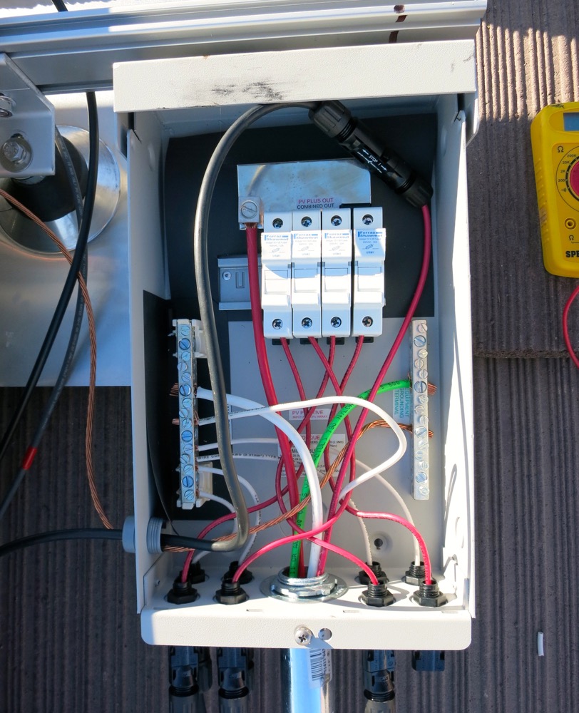
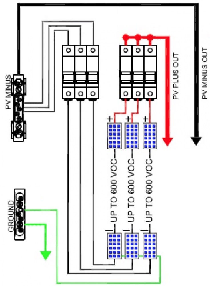
    It was discovered by Sensij (good eye on that one, would have totally missed it and just left it the way it is, so thank you) that since my inverter is transformerless, both the DC+ and the DC- need to have fuses. The combiner box I purchased only has the DC+ fused, but the DC- is going straight to the PV- bus bar.

    The simplest solution I can see if adding fuse holders on the DC- wires. There are 4 fuse holders already in the box and I only need 3 of them on the DC+ side, so I would need to add 2 more, which I believe there is space for on the DIN rail.

    Are there any potential issues you guys see which this plan?
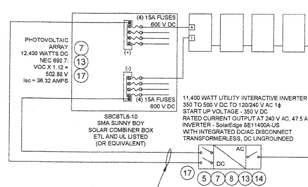


    From the permit:

  • sensij
    Solar Fanatic
    • Sep 2014
    • 5074

    #2
    Why not call Midnite Solar and see what they think of your plan to modify their box? Modifying a listed device is unlikely to be code compliant, but that doesn't mean it won't work. I think you are counting on an inspector who isn't going to be looking too hard, so why not? I pulled up the ETL listing for these boxes, and the MN4PV4-MC4 isn't even in there although the documentation for that box says it should be... I've not run into that before.

    I'll say it again here... white wire in an ungrounded DC circuit is an obvious noncompliance, and should be something any competent inspector would fail you on / make you fix. You could at least make an attempt to hide it by permanently marking the white conductor as black (or some other unreserved color) at each termination point, and wave 200.7(C)(1) at it as justification even though that really wouldn't apply.

    Just one other point, and then I think I'm done with this... NEC 110.12 requires electrical equipment to be installed in a neat and workmanlike manner. It is a vague requirement, but an inspector who sees lots of broken or separated wire strands that haven't been inserted into the lug or busbar properly may sharpen their attention to everything else. I'll give you credit for trying to pull this together after your installer screwed you, and for openly sharing pictures of your work and subjecting yourself to criticism / judgement, but just because it makes power doesn't mean it was done right.
    CS6P-260P/SE3000 - http://tiny.cc/ed5ozx

    Comment

    • inetdog
      Super Moderator
      • May 2012
      • 9909

      #3
      I think that you are going farther than necessary in fusing. There is, AFAIK, no requirement that the individual strings have both legs fused. A single fuse on the negative output of the combiner in the same place as the OCPD on the + combiner output should meet safety needs and probably satisfy the requirements of the NEC.
      (I am open to other opinions on this, of course.)
      SunnyBoy 3000 US, 18 BP Solar 175B panels.

      Comment

      • sensij
        Solar Fanatic
        • Sep 2014
        • 5074

        #4
        SolarEdge has an NEC compliance document that specifically states:

        Note: In rare cases where three or more strings of power optimizers are wired in parallel, fusing will be required to protect the wiring between the power optimizers and the inverter. Because the circuit conductors are not grounded, fuses would be required in both the negative and positive conductors. The recommend fuse size of 20 Amps is calculated using the 15 Amp continuous output current limit of the power optimizer multiplied by 1.25 in accordance with NEC Articles 210.19 and 240.4.
        A 20 A fuse wouldn't make sense installed on the output of the combiner, I believe they are recommending fuses on each string. Also, for what it is worth (and in this installation, not much), fuses on the + and - of each string were called out on the permit.
        CS6P-260P/SE3000 - http://tiny.cc/ed5ozx

        Comment

        • HX_Guy
          Solar Fanatic
          • Apr 2014
          • 1002

          #5
          Originally posted by inetdog
          I think that you are going farther than necessary in fusing. There is, AFAIK, no requirement that the individual strings have both legs fused. A single fuse on the negative output of the combiner in the same place as the OCPD on the + combiner output should meet safety needs and probably satisfy the requirements of the NEC.
          (I am open to other opinions on this, of course.)


          as pointed out by sensij, the SolarEdge paperwork mentions it as does my permit, and also an article I found online referencing NEC code.

          From SolarEdge:

          Note: In rare cases where three or more strings of power optimizers are wired in parallel, fusing will be required to protect the wiring between the power optimizers and the inverter. Because the circuit conductors are not grounded, fuses would be required in both the negative and positive conductors. The recommend fuse size of 20 Amps is calculated using the 15 Amp continuous output current limit of the power optimizer multiplied by 1.25 in accordance with NEC Articles 210.19 and 240.4.
          From my building permit:


          Additionally, this article here talks about the NEC code requirements: http://ecmweb.com/nec/wiring-methods-pv-systems-and-nec

          In a transformerless inverter, neither the positive nor negative conductor has a bond to ground. The result is that you no longer have a grounded current-carrying conductor. This requires both conductors in each circuit to be protected with OCPDs and have disconnecting means as required in Art. 690, Part III.

          Comment

          • HX_Guy
            Solar Fanatic
            • Apr 2014
            • 1002

            #6
            Originally posted by sensij

            I'll say it again here... white wire in an ungrounded DC circuit is an obvious noncompliance, and should be something any competent inspector would fail you on / make you fix. You could at least make an attempt to hide it by permanently marking the white conductor as black (or some other unreserved color) at each termination point, and wave 200.7(C)(1) at it as justification even though that really wouldn't apply.
            Sensij do you have any suggestions how I would go about permanently marking it black? I believe my inspection is tomorrow so not a lot of time.

            Comment

            • sensij
              Solar Fanatic
              • Sep 2014
              • 5074

              #7
              Originally posted by HX_Guy
              Sensij do you have any suggestions how I would go about permanently marking it black? I believe my inspection is tomorrow so not a lot of time.
              A sharpie will get the job done, although there are better more permanent markers, tapes, and paints out there. If you notch the tip, it makes it a little easier.
              CS6P-260P/SE3000 - http://tiny.cc/ed5ozx

              Comment

              • Amy@altE
                Solar Fanatic
                • Nov 2014
                • 1023

                #8
                Is that 4th fuse even connected to the positive bus bar? I can't see a finger going into the top from the picture.

                Midnite allows you to use the DIN rail to hold fuse holders and breakers that are not all bussed together, so if you can get a 5th fuse holder and a 60A (15A x 4 strings) fuse to fit on that din rail, you are not breaking any Midnite rules. They do say you can fit 6 breakers or 4 fuse holders, so I'm not sure if there is room for one more.

                The best suggestion to change the white wire to black is black electrical tape on both ends. NEC allows you to turn some black wire white by doing that, it is a bit of a stretch to turn white wire to black, but depending on your AHJ, you may be able to get away with it.
                Solar Queen
                altE Store

                Comment

                • Amy@altE
                  Solar Fanatic
                  • Nov 2014
                  • 1023

                  #9
                  Originally posted by Amy@altE
                  The best suggestion to change the white wire to black is black electrical tape on both ends. NEC allows you to turn some black wire white by doing that, it is a bit of a stretch to turn white wire to black, but depending on your AHJ, you may be able to get away with it.
                  Let me change that to the best suggestion I have. Sensij's suggestion is better.
                  Solar Queen
                  altE Store

                  Comment

                  • HX_Guy
                    Solar Fanatic
                    • Apr 2014
                    • 1002

                    #10
                    Originally posted by Amy@altE
                    Is that 4th fuse even connected to the positive bus bar? I can't see a finger going into the top from the picture.

                    Midnite allows you to use the DIN rail to hold fuse holders and breakers that are not all bussed together, so if you can get a 5th fuse holder and a 60A (15A x 4 strings) fuse to fit on that din rail, you are not breaking any Midnite rules. They do say you can fit 6 breakers or 4 fuse holders, so I'm not sure if there is room for one more.

                    The best suggestion to change the white wire to black is black electrical tape on both ends. NEC allows you to turn some black wire white by doing that, it is a bit of a stretch to turn white wire to black, but depending on your AHJ, you may be able to get away with it.
                    The 4th fuse is connected, it has this skinny leg that extends out to it like this:


                    As for the DIN rain, I do believe it will fit 6 fuses. It would require me to flip the positive bus bar around and cut off the end (which apparently how it was previously done when you only needed 4 fuses and Midnite Solar only offered a 6 fuse box, per their installation manual, so I'm thinking that's not a problem to cut it?). Figuring that all 6 fuse holders fit on the rail, it would look something like this.

                    I thought about adding a second bus bar instead of going down with separate wires but I don't like how close the positive and negative bus bars would be to each other.

                    One other question...if the fuse holders don't all fit on the DIN rail, say only 5 fit, is there an issue with securing one fuse holder off the rail? Does it have to be rail mounted?

                    Comment

                    • Amy@altE
                      Solar Fanatic
                      • Nov 2014
                      • 1023

                      #11
                      Aha, ok, the gap above the fuse holder had me worried.

                      If that's a PV6, it can hold 6 breakers, but only 4 fuse holders, the fuse holders are wider than a breaker. And even if it fit 6, you need 8, unless you have one 60A fuse for the combined 4 negatives coming off the negative bus bar (I really don't like that idea, but might possibly work). Someone correct me if you are required by code to have OCP on each string, or if you can do it after it is combined.

                      As I'm sure you know by now, the right product to use for a TL inverter is Midnite's MNPVHV8-DLTL-4X. If you don't have to have it disconnectable at the array (because you are using the SolarEdge, they comply with NEC2014 Rapid Shutdown without a disconnecting combiner box), you may be able to use the MNPV12 with 8 fuse holders and fuses. It can hold up to 10, and they are divided into 2 circuits, up to 5 fuses each.

                      I think you'll have a much better chance passing inspection if you reschedule and get the right box, especially since the wire color may have the inspector questioning the rest of the install.
                      Solar Queen
                      altE Store

                      Comment

                      • HX_Guy
                        Solar Fanatic
                        • Apr 2014
                        • 1002

                        #12
                        Amy, I actually only need 6 total fuses, not 8. I have 3 strings in the system...right now the 4th fuse holder (far right) isn't being utilized.
                        The box is a MNPV4-MC4, but it's really a PV6 that's pre-wired with MC4 connectors for 4 strings (same box though).

                        My install does not require it to be disconnect able at the array. I have looked at the MNPV12, which has enough fuse holders, and it would definitely work...it's basically what I'm trying to build.


                        The other option is the SMA SBCBTL6 combiner, which is specifically for this purpose. Again basically does the same thing, but like with the above Midnite Solar, it's pretty oversized for my application since I only need 6 total fuses for 3 strings.

                        Comment

                        • HX_Guy
                          Solar Fanatic
                          • Apr 2014
                          • 1002

                          #13
                          Was able to talk to tech support at Midnite Solar and they said that while the box hasn't been tested for what I'm proposing and it would lose it's UL listing if modified in this way, he didn't see why it wouldn't work. He said there should be just enough same on the DIN rail to fit 6 fuse holders and actually even gave me the suggestion that I could cut out the opening in the black dead front wider so that it would fit around all 6 fuses and also keep then together so they don't fall off the rail.


                          Also here is another picture I found online that shows the available space on the DIN rail, definitely looks like 2 more fuses would fit on there.

                          Comment

                          • HX_Guy
                            Solar Fanatic
                            • Apr 2014
                            • 1002

                            #14
                            Originally posted by Amy@altE
                            Let me change that to the best suggestion I have. Sensij's suggestion is better.
                            What do you guys think of this stuff?


                            It's heat shrink tubing that's rated for 600V and 125ºC flammability. 10mm that shrinks down to 5mm (wire diameter is 6mm).

                            Comment

                            • sensij
                              Solar Fanatic
                              • Sep 2014
                              • 5074

                              #15
                              Nice. I was going to suggest heat shrink as a clean looking option, but didn't think you would have it available. I would definitely use that instead of a sharpie.
                              CS6P-260P/SE3000 - http://tiny.cc/ed5ozx

                              Comment

                              Working...