X
 
  • Time
  • Show
Clear All
new posts
  • bhvm
    Member
    • Jun 2014
    • 46

    #46
    Hello everyone and Thanks for Concerns and sincere help.

    I have recieved my Charge controller, and in one fell swoop- ITs WORTH THE WEIGHT IN GOLD.

    The controller is very advanced and has all the functions as the seller promised. A few advanced ones are-
    1) Boost charging with equalizing function
    2) Temperature compensated charging with Ambient sensor and battery temperature probe
    3) FULL MPPT function
    4) Ability to set Charging Current, Float Voltage, Boost Voltage, Float timing, Equalizing voltage.
    5) Full Load control with user settings. Load ampere measurement. Low voltage disconnect, Overload protection
    6) Power saving relay that shifts load to inverter (Battery) when the solar energy is ample.

    I must say this is a godsend controller priced at just 200$.

    I have currently hooked it up to my house on a small system as follows-
    2x 150AH 12v batteries in Parallel
    2x 200W solar panels in parallell (VOC 44v, VMP 37v, IMP 5.4A, ISC 5.8A)
    20A Above said MPPT controller.

    In current weather with slight clouds i am Seeing the MPPT make upto 16 Amps from 7A Incoming current. I am expecting full 20A in full Sun.

    I will post the images of setup soon.
    thanks.

    P.s. My larger 1000W (250w x 4 ) setup is still pending as the 24v 40A MPPT controller is yet to arrive.
    Comment

    • tufail_74
      Junior Member
      • Apr 2012
      • 13

      #47
      Why still using parallel panels in array. You can make them series to get lesser current but same power. You have to consider the Vmax input of charge controller. Till then you can make them parallel that will help you reduce wire size.

      Comment

      • bhvm
        Member
        • Jun 2014
        • 46

        #48
        Originally posted by tufail_74
        Why still using parallel panels in array. You can make them series to get lesser current but same power. You have to consider the Vmax input of charge controller. Till then you can make them parallel that will help you reduce wire size.
        Max voltage support for controller is 70v. as in already using 44v panles for 12v Battery, I can't series them As they'll exceed 70v

        for the cables we are using 5.sqmm for panels and 6 sqmm for Battery to controllers.

        Comment

        • bhvm
          Member
          • Jun 2014
          • 46

          #49
          Here are the images I promised.

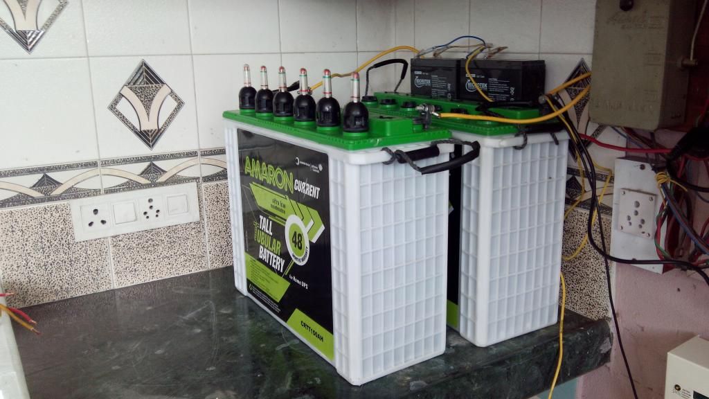
          My battey bank and Inverter setup-


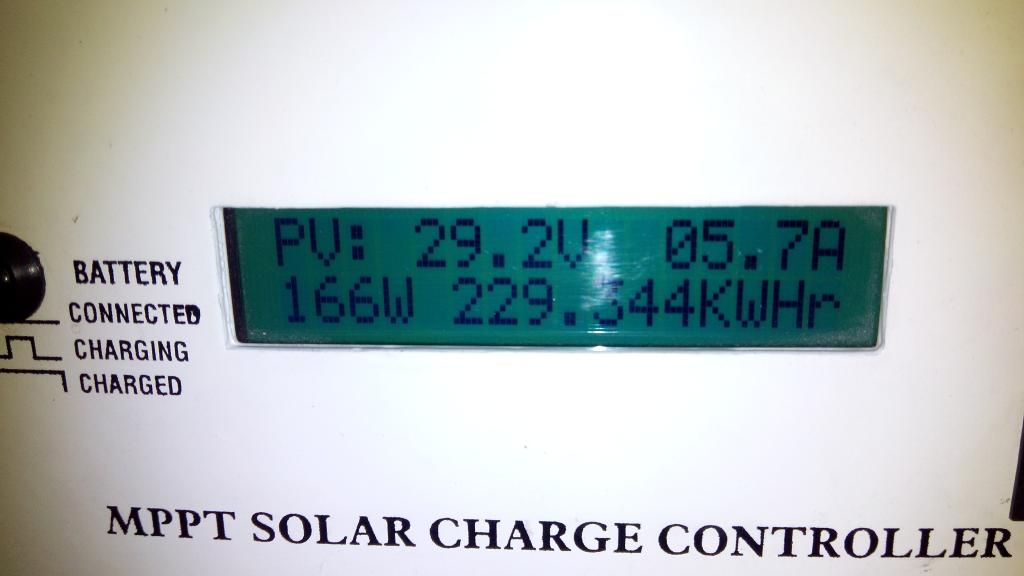
          Getting 5.7 Amps from Panels


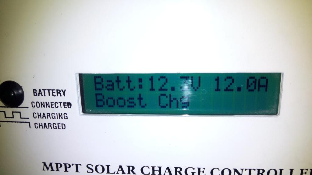
          The MPPT making 12 Amps out of it!


          Temperature compensated charging-


          My sweet controller-


          The DC 12V LED wiring and lights at my house-

          Comment

          • Sunking
            Solar Fanatic
            • Feb 2010
            • 23301

            #50
            Wished I had some more time but you have some serious wiring issues. I should be seeing two sets of wires on the battery post, one from the controller and one going to the inverter. Undersized wire. Not a single breaker or fuse on the batteries.
            MSEE, PE

            Comment

            • mapmaker
              Solar Fanatic
              • Aug 2012
              • 353

              #51
              Originally posted by Sunking
              Wished I had some more time but you have some serious wiring issues. I should be seeing two sets of wires on the battery post, one from the controller and one going to the inverter. Undersized wire. Not a single breaker or fuse on the batteries.
              I'm not too sure of what I am seeing, but ideally there would be one wire on each battery post (going to a bus bar). Since he is NOT using a bus bar, there should be either 1 or 3 wires per battery post... the post where you see wires to the inverter and controller should have a third wire to parallel the two 12 volt batteries.

              --mapmaker
              ob 3524, FM60, ePanel, 4 L16, 4 x 235 watt panels

              Comment

              • bhvm
                Member
                • Jun 2014
                • 46

                #52
                Originally posted by Sunking
                Wished I had some more time but you have some serious wiring issues. I should be seeing two sets of wires on the battery post, one from the controller and one going to the inverter. Undersized wire. Not a single breaker or fuse on the batteries.
                Take your time sir,
                1) The wires used are 10 SQMM for Inverter and Interconnection, and 6 SQmm for solar charge controller. They're neatly tucked behind battery so not visible. manufacturer recommendation was 4 SQMM but we went overkill.
                2) The Fuse box is under the charger controller, Half visible in the picture (Ceramic fuese)
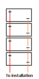
                3) The Batteries are in Staggered (Diagonal) parallel to distribute the load, as mentioned by experts here.

                Comment

                • bhvm
                  Member
                  • Jun 2014
                  • 46

                  #53
                  Originally posted by mapmaker
                  I'm not too sure of what I am seeing, but ideally there would be one wire on each battery post (going to a bus bar). Since he is NOT using a bus bar, there should be either 1 or 3 wires per battery post... the post where you see wires to the inverter and controller should have a third wire to parallel the two 12 volt batteries.

                  --mapmaker
                  The Wires are exactly as you said , map maker. Just that they're in a staggered parallel for the good.
                  I'll post a close up pic later on.

                  Thanks.

                  Comment

                  Working...