
 Tweet
Tweet
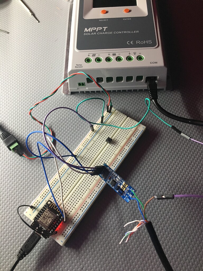
Now that I figured out that the Tracer 2210A mppt charge controller does not log data, I want to use an Arduino Uno to do that.
I found and Arduino Sketch which will capture the data to the Arduino IDE Terminal. I can later on send the data to an SD card or use an IoT wifi module.
I have a standard network cable which I have cut one of the ends off so I can access the wires. My problem is Which Wires on the cut end, that connect to the Arduino Uno (pins 10 & 11) do I actually use? I can try all of them but that would take a while plus I might mess up the 2210A charge controller or the Arduino itself if I use the incorrect ones.
(I tried using one RS-485-B and one RS-485-A pin but no results came up in the IDE Terminal)
Any help will be really appreciated.
Thanks in advance.
Chris
According to the 2210A documentation, the pins are laid out the following way:
PIN Function
1 Power supply output +5
2 Power supply output +5
3 RS-485-B
4 RS-485-B
5 RS-485-A
6 RS-485-A
7 Ground
8 Ground
The Arduino Sketch I am using follows:
| /* | |
| * An interface to the Tracer solar regulator. | |
| * Communicating in a way similar to the MT-5 display | |
| */ | |
| #include <SoftwareSerial.h> | |
| SoftwareSerial myserial(10, 11); // RX, TX | |
| uint8_t start[] = { 0xAA, 0x55, 0xAA, 0x55, 0xAA, 0x55, | |
| 0xEB, 0x90, 0xEB, 0x90, 0xEB, 0x90 }; | |
| uint8_t id = 0x16; | |
| uint8_t cmd[] = { 0xA0, 0x00, 0xB1, 0xA7, 0x7F }; | |
| uint8_t buff[128]; | |
| void setup() { | |
| Serial.begin(57600); | |
| myserial.begin(9600); | |
| } | |
| float to_float(uint8_t* buffer, int offset){ | |
| unsigned short full = buffer[offset+1] << 8 | buff[offset]; | |
| return full / 100.0; | |
| } | |
| void loop() { | |
| Serial.println("Reading from Tracer"); | |
| myserial.write(start, sizeof(start)); | |
| myserial.write(id); | |
| myserial.write(cmd, sizeof(cmd)); | |
| int read = 0; | |
| for (int i = 0; i < 255; i++){ | |
| if (myserial.available()) { | |
| buff[read] = myserial.read(); | |
| read++; | |
| } | |
| } | |
| Serial.print("Read "); | |
| Serial.print(read); | |
| Serial.println(" bytes"); | |
| for (int i = 0; i < read; i++){ | |
| Serial.print(buff[i], HEX); | |
| Serial.print(" "); | |
| } | |
| Serial.println(); | |
| float battery = to_float(buff, 9); | |
| float pv = to_float(buff, 11); | |
| //13-14 reserved | |
| float load_current = to_float(buff, 15); | |
| float over_discharge = to_float(buff, 17); | |
| float battery_max = to_float(buff, 19); | |
| // 21 load on/off | |
| // 22 overload yes/no | |
| // 23 load short yes/no | |
| // 24 reserved | |
| // 25 battery overload | |
| // 26 over discharge yes/no | |
| uint8_t full = buff[27]; | |
| uint8_t charging = buff[28]; | |
| int8_t battery_temp = buff[29] - 30; | |
| float charge_current = to_float(buff, 30); | |
| Serial.print("Load is "); | |
| Serial.println(buff[21] ? "on" : "off"); | |
| Serial.print("Load current: "); | |
| Serial.println(load_current); | |
| Serial.print("Battery level: "); | |
| Serial.print(battery); | |
| Serial.print("/"); | |
| Serial.println(battery_max); | |
| Serial.print("Battery full: "); | |
| Serial.println(full ? "yes " : "no" ); | |
| Serial.print("Battery temperature: "); | |
| Serial.println(battery_temp); | |
| Serial.print("PV voltage: "); | |
| Serial.println(pv); | |
| Serial.print("Charging: "); | |
| Serial.println(charging ? "yes" : "no" ); | |
| Serial.print("Charge current: "); | |
| Serial.println(charge_current); | |
| delay(1000); | |
| } | |


Comment