-
-
I think you are saying the ground slopes up at the west end. The array in my first picture slopes about half a dozen feet over
its 66' length; it follows the ground. Its perfectly straight because I used a laser to set it up. This may not be very conventional,
but its not a building, and the panels work just as well. I'm still waiting for someone to tell me some rules were broken. Bruce Roe
Comment
-
Powerfab top of pole PV mount (2) | Listeroid 6/1 w/st5 gen head | XW6048 inverter/chgr | Iota 48V/15A charger | Morningstar 60A MPPT | 48V, 800A NiFe Battery (in series)| 15, Evergreen 205w "12V" PV array on pole | Midnight ePanel | Grundfos 10 SO5-9 with 3 wire Franklin Electric motor (1/2hp 240V 1ph ) on a timer for 3 hr noontime run - Runs off PV ||
|| Midnight Classic 200 | 10, Evergreen 200w in a 160VOC array ||
|| VEC1093 12V Charger | Maha C401 aa/aaa Charger | SureSine | Sunsaver MPPT 15A
solar: http://tinyurl.com/LMR-Solar
gen: http://tinyurl.com/LMR-ListerComment
-
Putting a rebar structure inside the column shouldn't be a problem.. thanks for the advice.. The Ironridge system wants me to sink the 3 inch sch40 pipe to a depth of 3.5ft below grade anyhow.. Attaching some rebar to it should be easy enough. My system is going to be 38 feet long (4 panels high) and my max spacing between support columns is only 9ft-7in..
I will also be adding cross bracing.. it should be quite stiff.Comment
-
Maybe I missed something. Does any review/approval by AHJ, if required, possibly include any check for structural with respect to expected loadings ? If so, will the design be checked against any Ironridge calcs/ B.M.'s/drawings ? NOMB, just suggesting a heads' up answer if someone asks.Comment
-
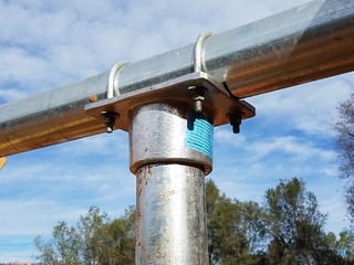
Dang it - I was hoping I had some photos of the inside of the Iron Ridge cap but all I took was the outside. Here is a cap on one of my 3" vertical pipes before cementing. The cap is a snug fit and inside of the cap it is a flat surface for the entire inside. The pipe you cut rests against that flat surface. If you don't square cut it - that cap will wobble a tad (not much since the cap is snug) and you will have unequal pressure on that aluminum plate. Then you have two set screws that spike into the 3" pipe side to hold the cap in place. If you cut that end so its a perfect square cut, that cap by definition will be square so your horizontal pipe will then be square to the vertical pipe. If its not square cut, there will be some wobble and it will simply make more work aligning all of that up. You have the equipment so your good.
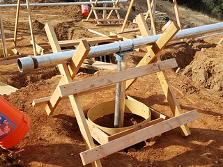
Here is the vertical pipe hanging freely in the hole ready for cement. Having the cap square ensures that pipe is hanging vertically as long as the horizontal is level. This is where the square cut really helps. The pipe bottom is 1/3 of the ground hole length off of the bottom of the hole per Iron Ridge specs and it will fill inside with cement when you pore it. If you click into the full picture you can see the two set screws.
Comment
-
It's real easy to find fault w/ other's work and often a cheap shot, but I'd have not used slotted holes in the flat plates, and I'd have used double nuts or lock washers, and made the washers larger if possible. All that said, I'd have a hard time doing better on the construction end.Comment
-
Thanks for the photos! I really like the way you supported the posts with the wood structure.
For the price, I would have thought Ironridge would have used stainless steel U-Bolts.. They look like hot-dipped galvanized..
Nice work! I'd love to see more photos.. Clicked through flikr to see your project.. pretty cool..
How do you like the Harbor Freight cement mixer? Did it hold up?
Comment
-
B.M. == Bills of Material. == Listing and description of the stuff shown on design drawings that describe the material in enough detail to ensure the same stuff that was used in the engineering of the design actually gets used in the design. One of the three usually necessary preliminary outputs of a design process: Calculations, Drawings, Bills of Material.
NOMB == None Of My Business.Comment

 Tweet
Tweet


Working...
😀
😂
🥰
😘
🤢
😎
😞
😡
👍
👎
☕
Comment