
 Tweet
Tweet
A little background - I do not have an electrical background, but I am in the process of installing a ground mount system with (25) 305 watt panels, in two strings, connected to an SMA Sunny Boy 7.0 transformerless string inverter. I did re-wire all the outlets and lights when we renovated our house, so I do have some experience in straightforward electrical work.
I live in an area where coal is king and electric rates are very low, so there is little-to-no solar being installed, and no installers nearby, and electricians are not familiar with solar. Hence, I am doing it myself. I did re-wire all the outlets and lights when we renovated our house, so I do have some experience is straightforward electrical work. When I pulled the permit for the solar, the local inspector did not require a drawing, and told me straight out that he has no experience with solar, so I am on my own to ensure that the panels and inverter are wired correctly.
I feel pretty confident in everything except for the grounding. I have found so much information and so many drawings online that seem to conflict and I am a little paranoid about frying my equipment.
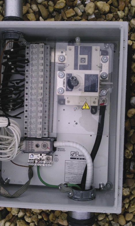
My panels are getting mounted on Ironridge XR rails, and bonded with UFO connectors. Each of the rails will have a grounding lug with a 6 gauge wire connecting them. Here is where I get a little fuzzy. Should that 6ga wire then be connected to a grounding rod in the earth, or should it go back to the inverter and get connected to the equipment grounding terminal? I know that I am misunderstanding, but in the inverter manual it says, "Do not operate grounded PV modules together with this product. Only ground the mounting frames of the PV modules."
I have seen line drawings where the ground wire connects to a grounding rod and then goes to the inverter, and I have seen some drawings where the ground wire from the panels goes straight to the inverter.
A little helpful input would be appreciated.
I live in an area where coal is king and electric rates are very low, so there is little-to-no solar being installed, and no installers nearby, and electricians are not familiar with solar. Hence, I am doing it myself. I did re-wire all the outlets and lights when we renovated our house, so I do have some experience is straightforward electrical work. When I pulled the permit for the solar, the local inspector did not require a drawing, and told me straight out that he has no experience with solar, so I am on my own to ensure that the panels and inverter are wired correctly.
I feel pretty confident in everything except for the grounding. I have found so much information and so many drawings online that seem to conflict and I am a little paranoid about frying my equipment.
My panels are getting mounted on Ironridge XR rails, and bonded with UFO connectors. Each of the rails will have a grounding lug with a 6 gauge wire connecting them. Here is where I get a little fuzzy. Should that 6ga wire then be connected to a grounding rod in the earth, or should it go back to the inverter and get connected to the equipment grounding terminal? I know that I am misunderstanding, but in the inverter manual it says, "Do not operate grounded PV modules together with this product. Only ground the mounting frames of the PV modules."
I have seen line drawings where the ground wire connects to a grounding rod and then goes to the inverter, and I have seen some drawings where the ground wire from the panels goes straight to the inverter.
A little helpful input would be appreciated.


Comment