Questions regarding battery type and what voltage moving forward

Collapse
X
 
  • Time
  • Show
Clear All
new posts
  • georgia088
    Member
    • Sep 2018
    • 71

    #76
    Originally posted by venquessa
    For your anti-parallel circuit I would look at SSRs/Relays. If you look at the pinout for them you will typically find they have at least 3 dry poles, sometimes 4. STDP and DTDP. Usually they refer to the contacts as "Normally closed" and "Normally open". They cannot be in both states (do check they are break-before-made though, there are specialist transfer relays which have "make-before-break" mechanics. You might find these in say a UPS.

    So it's up to you if you want to go with mosfets as additional protection or, you could consider more physical protections like reverse polarity diode and fuse. For over voltage you can do similar with zener diodes (let them go short with the fuse when an over-voltage occurs). If nothing critical is running off the system this is the cheapest protection. The only downside is... if/when you engage that protection it destroys itself pretty much in the process of saving everything else.

    If you haven't yet looked into it. I'd start there. If you want to control the mosfets from the MCU you have to consider that the vast majority of mosfets require up to 10V/-10V on the gate and the gate capacitance can mean to get the stated ~nanosecond rise time through the resistive region, can require 3 Amp current spike. None of those things are things ESP32s or Arduinos like.
    To be honest, I am only looking for an added protection with the mosfets because you suggested it. Although obviously added protection especially for a dummy like me is better, it is also something else for me to screw up in design or break down once in use.

    I honestly feel comfortable with only the two ssr design in which one single I/O pin is used to trigger one or the other of the relays (12 or 24v reduced to 12v). Assuming there is nothing holding charge in the ssr, I think it would be relatively safe. I assume it would be relatively rare for one or both ssr’s get stuck in the on or off position. In the event this happens, you either get no power or a 12v source would be supplying a 12v source. Obviously not good, but as I think you said earlier probably no “boom” just agonizing death for one or both batteries…..$$$$.

    I have a project that has been running well over a year with a fortek ssr (“puck” style). It too is running off of a wemos d1 mini (esp8226). I guess I’m just comfortable with them, but it sounds as if I need to familiarize myself with the esp32. The fortek ssr in this case is switching an ac load. These forteks get a bad wrap for there being so many counterfeits out there, but I’ve had good success. I am thinking of going with two of these (obviously high amp dc versions). Now to the issue:

    In the project described above, I had to connect the 5v pin from the wemos (receiving power from usb cable) to the signal side of the SSR. To “switch” the SSR, I had to have my I/O sink to LOW to switch the SSR. The reason for this I assume was the 3.3v esp board didn’t supply enough voltage to switch the SSR. By supplying the 5v from the cable and the ground from the wemos I/O pin this allowed the switching.

    In order to have one pin switch two different SSR’s, I would need to be able to use both the LOW and HIGH side logic. Not sure the esp board will be capable of providing this on its own. Obviously, I can add a transistor or something to ensure the switching, but because I am wanting the timing to be simultaneous, I assume I would need to use the transistor for both the HIGH and LOW logic if the esp board is unable to switch with its 3.3v and current limits?

    Am I missing something, is there an easier way?

    THANKS!!
    Comment

    • jflorey2
      Solar Fanatic
      • Aug 2015
      • 2331

      #77
      Originally posted by georgia088
      I’m a little confused about what you’re talking about when a cell under volts. If a cell under volts at 2.5 and there is not cell balancing with a bms, The solar is still collecting power, but there is no where to put it because the battery has “disconnected”
      When this happens, two things occur:

      1) The controller, seeing very high impedance into the battery, tends to regulate at its maximum voltage. Good ones will be bang-on their max voltage. Lesser controllers will wander around because they were not designed to be stable with no load - but will be close to their max voltage. This may confuse since the voltage at the battery terminals will be high even though the battery is close to 0% charge.

      2) The battery, if well designed, will present a high resistance across the turnoff FET. Thus the battery will (slowly) charge through that resistance as long as it has not gone below about 1 volt per cell. Once it hits around 2.7V per cell it will reconnect and the battery will charge as normal.

      Needless to say you never want this to actually happen, which is why you set minimum inverter LVD well above 2.5 volts per cell.

      Comment

      • venquessa
        Member
        • Feb 2018
        • 53

        #78
        There are differences in responses. A BMS with a FET bridge can block current in either direction independently. A BMS with a single mosfet (or paralleled up) can only break it in one direction, (*) and a back to back config (probably most common) will break both at the same time.

        A fuse obviously breaks both.

        Part of the concern is what happens to the flowing current at exactly the moment the mosfets go off and how fast they go off. A 40A MPPT unit might have an inductor which weighs a kilogram. That is a huge amount of magnetic field to simply get rid of. We hope the particular MPPT controller we use handles this.... should it ever be required to. Either borrow from "Hope" or borrow from the bank and buy big brand, big bucks.

        The other part of the concern is that blocking the discharge from the battery will remove the DC reference supply from the MPPT itself. Not all of them will run on solar power themselves. Seems a bit weird, right? But it will have significant impact on the topology of the design and feedback loops for it to do that. So when you pull the battery connection out of my 10A MPPT the screen goes blank and it switches off, regardless of what amps it was dealing with at the time.

        In this erroneous state which I found myself in accidentally with a corrosion stuck DP switch going faulty the moment the system powered up, I was measuring panel open circuit voltage on the panel side (41VoC) and a random phantom voltage swinging around 7V to -3V on the MPPT BATT terminals. I had bigger things to worry about than getting the scope out to find out how random or what shape that phantom voltage was.

        The manual says not to do this! I expect if it literally loses power, like a diode prevents it from running it's digital electronics from the panel side of the buck converter then all controll over that buck converter and it's mosfets are lost. That might even involve their gates floating around randomly. You should for example expect the potential (bad pun) of finding panel VoC on the battery terminals! The manufacturer makes zero claims as to what protection it has, or has not got (in my case), they just say NEVER run the unit with a panel connected without a battery connected FIRST.

        It is an interesting point on the mosfets being able to provide, within reason, very tiny amounts of resistence across the FET bridge to "push back" against the MPPT current.... or in this case, "pull back" by lowering it's voltage much harder and appearing to be at a lower voltage than it actually is.

        The trouble is... finding that out either requires extensive testing and extensive in field tests of the equipment or... borrow from luck, hope or the bank.

        (*) meh, caveats.
        Last edited by venquessa; 04-14-2023, 08:50 AM.

        Comment

        • georgia088
          Member
          • Sep 2018
          • 71

          #79
          Originally posted by venquessa
          There are differences in responses. A BMS with a FET bridge can block current in either direction independently. A BMS with a single mosfet (or paralleled up) can only break it in one direction, (*) and a back to back config (probably most common) will break both at the same time.

          A fuse obviously breaks both.

          Part of the concern is what happens to the flowing current at exactly the moment the mosfets go off and how fast they go off. A 40A MPPT unit might have an inductor which weighs a kilogram. That is a huge amount of magnetic field to simply get rid of. We hope the particular MPPT controller we use handles this.... should it ever be required to. Either borrow from "Hope" or borrow from the bank and buy big brand, big bucks.

          The other part of the concern is that blocking the discharge from the battery will remove the DC reference supply from the MPPT itself. Not all of them will run on solar power themselves. Seems a bit weird, right? But it will have significant impact on the topology of the design and feedback loops for it to do that. So when you pull the battery connection out of my 10A MPPT the screen goes blank and it switches off, regardless of what amps it was dealing with at the time.

          In this erroneous state which I found myself in accidentally with a corrosion stuck DP switch going faulty the moment the system powered up, I was measuring panel open circuit voltage on the panel side (41VoC) and a random phantom voltage swinging around 7V to -3V on the MPPT BATT terminals. I had bigger things to worry about than getting the scope out to find out how random or what shape that phantom voltage was.

          The manual says not to do this! I expect if it literally loses power, like a diode prevents it from running it's digital electronics from the panel side of the buck converter then all controll over that buck converter and it's mosfets are lost. That might even involve their gates floating around randomly. You should for example expect the potential (bad pun) of finding panel VoC on the battery terminals! The manufacturer makes zero claims as to what protection it has, or has not got (in my case), they just say NEVER run the unit with a panel connected without a battery connected FIRST.

          It is an interesting point on the mosfets being able to provide, within reason, very tiny amounts of resistence across the FET bridge to "push back" against the MPPT current.... or in this case, "pull back" by lowering it's voltage much harder and appearing to be at a lower voltage than it actually is.

          The trouble is... finding that out either requires extensive testing and extensive in field tests of the equipment or... borrow from luck, hope or the bank.

          (*) meh, caveats.
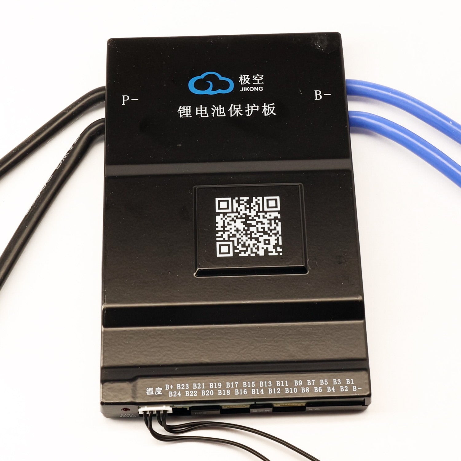
          I haven't abandon the project, however, I did get a bit side tracked. Although with a very similar project. My dad has a 48v golf cart that needs batteries. He wants to go lithium. Because I have been doing alot of reading about lifepo4 and bms's I convinced him for half the price it was worth attempting to build a battery pack from 16 105AH Lifeo4 cells instead of buying a drop in replacement. I've decided to go with the JK BMS. Do you have any experience with these? This is the unit:


          Thanks!

          Comment

          • Ampster
            Solar Fanatic
            • Jun 2017
            • 3649

            #80
            Originally posted by georgia088
            ........ My dad has a 48v golf cart that needs batteries. He wants to go lithium. Because I have been doing alot of reading about lifepo4 and bms's I convinced him for half the price it was worth attempting to build a battery pack from 16 105AH Lifeo4 cells instead of buying a drop in replacement. I've decided to go with the JK BMS. Do you have any experience with these? This is the unit:


            Thanks!
            There are some good reviews on that device at diysolarforum. I have also read some good reviews on that vendor but have no experience with them. I don;t use the JK BMS but I use the JK 2 Amp active balancer on my 840 Ahr staionary pack. I honestly prefer a conactor based BMS for anything with a motor load that could have a high Amp discharge. It is alos a good way to have a positive battery disconnect. i left the battery switch on one time for a few days or weeks on a 72 volt Gem vehicle and the Nissan Leaf modules discharged and swelled to the point that they were uselses. It was a temporary installation and needless to say I did not anticipate the draw of the DC to DC converter that ran the accesories. I also did not have a BMS whose low voltage disconnect would have protected them. JBD makes a 16S BMS that has a contacroer which is good up to 200 Amps.
            9 kW solar, 42kWh LFP storage. EV owner since 2012

            Comment

            • georgia088
              Member
              • Sep 2018
              • 71

              #81
              Originally posted by Ampster

              There are some good reviews on that device at diysolarforum. I have also read some good reviews on that vendor but have no experience with them. I don;t use the JK BMS but I use the JK 2 Amp active balancer on my 840 Ahr staionary pack. I honestly prefer a conactor based BMS for anything with a motor load that could have a high Amp discharge. It is alos a good way to have a positive battery disconnect. i left the battery switch on one time for a few days or weeks on a 72 volt Gem vehicle and the Nissan Leaf modules discharged and swelled to the point that they were uselses. It was a temporary installation and needless to say I did not anticipate the draw of the DC to DC converter that ran the accesories. I also did not have a BMS whose low voltage disconnect would have protected them. JBD makes a 16S BMS that has a contacroer which is good up to 200 Amps.
              Thanks! I went and read some reviews. They sounded good enough, and he is impatient and could pick the JK BMS up locally so he got it. I haven't installed it yet, but I will be in the next few days. Hopefully it will work.

              The initial starting of the JK unit appears to be different for different users. For some, the bms has to see a 2-5v higher voltage (as if it were charging) to power up. Some people claim the bms starts up automatically, some are using a seperate power supply to "fake the voltage", some are using a power switch to turn it on/off. I got the power switch. I am hoping this power switch will turn the bms on/off without the need for anything else. This really doesn't make sense to me why it would be this way.

              Thanks!

              Comment

              • venquessa
                Member
                • Feb 2018
                • 53

                #82

                I am testing 2 JK-BMSs. I did a successful low voltage disconnect with it. It produces lovely high-res data to play with. The app works fine. Picking the right one and then matching the accessories to it can be a challenge. If you go with one, be extremely gentle with the connectors. Don't ask

                As Ampster says though, a mosfet bridge isn't ideal under higher currents and usually only disconnects the low side. How many amps does a stationary golf cart, if "floored", pull at stall current? If someone does that in a "mostly flat" battery the current may spike the cell voltage collapse and the BMS will have to cut those amps. "Off Grid Garage" managed to destroy a JK-BMS by testing the overcurrent protection feature. It did it's job, but it died in the process. What if it died short?

                Fuses and breakers add more protection, but you need to be careful with picking the right kinds.

                Ideally with proper load and charge management the BMS, Fuses, nor breakers should be employed.

                The golf cart speed/motor controller should (you would hope) have features like soft start and it's own current limiting and battery disconnect. Much smaller speed controllers (for RC aircraft) for "weening power" which is basically "limp home mode", such that when the battery (or a cell) reaches a low tolerance voltage the output of the speed controller becomes current limited to not push the battery lower. Giving you enough time to land, or get the golf cart back to the charger. It also helps prevent a cell undervolt.

                Comment

                • georgia088
                  Member
                  • Sep 2018
                  • 71

                  #83
                  Originally posted by venquessa

                  Dogs nuts, JK-BMS is £35ish. £70 for the big ones. Cheaper ones with passive balancing and over/undervolt and even bluetooth are extremely common. There is a reason for that. The same factories that make them for LFP pack manufacturers sell them out the back door on Ali*/BG/Feebay/amazon. The difficulty there is knowing what you need and hoping it's what you ordered.
                  There is such good information in this thread, I went back and reread most of it. I know it is covering a wide variety of topics, but it is still great info!

                  venquessa I knew you had discussed a brand of bms earlier in the thread, so I went and found it. Sure enough it was the very one I am actually going to use. I will playing with it as I attempt to build the battery pack for the golf cart. I will post my results and or questions here. I hope the moderators don't care that I am mixing and matching the thread, but it all kind of goes together.

                  Thanks!

                  Comment

                  • georgia088
                    Member
                    • Sep 2018
                    • 71

                    #84
                    Originally posted by venquessa
                    I am testing 2 JK-BMSs. I did a successful low voltage disconnect with it. It produces lovely high-res data to play with. The app works fine. Picking the right one and then matching the accessories to it can be a challenge. If you go with one, be extremely gentle with the connectors. Don't ask

                    As Ampster says though, a mosfet bridge isn't ideal under higher currents and usually only disconnects the low side. How many amps does a stationary golf cart, if "floored", pull at stall current? If someone does that in a "mostly flat" battery the current may spike the cell voltage collapse and the BMS will have to cut those amps. "Off Grid Garage" managed to destroy a JK-BMS by testing the overcurrent protection feature. It did it's job, but it died in the process. What if it died short?

                    Fuses and breakers add more protection, but you need to be careful with picking the right kinds.

                    Ideally with proper load and charge management the BMS, Fuses, nor breakers should be employed.

                    The golf cart speed/motor controller should (you would hope) have features like soft start and it's own current limiting and battery disconnect. Much smaller speed controllers (for RC aircraft) for "weening power" which is basically "limp home mode", such that when the battery (or a cell) reaches a low tolerance voltage the output of the speed controller becomes current limited to not push the battery lower. Giving you enough time to land, or get the golf cart back to the charger. It also helps prevent a cell undervolt.
                    You can disregard the reply above. I didn't see your latest reply until now.

                    As to how many amps a golf cart will pull when "floored" that is quite a debate from what I have read. From what I have read, it depends largely on the type of motor used. The series motors are less efficient and pull more amps than the SepEx motors. The one I am installing on is a SepEx. I have never tried to see how many amps are pulled during a stall or "floored" event, so I honestly don't know what this particular cart will pull. I do know that most all drop in replacement batteries are using the 1C lifepo4 batteries at as low as 30-60Ah for continuous use and only short bursts of 2-3C. This seems extremely low to me, but again I don't know. The batteries I am using are only 1C rated but the same 105Ah lifepo4 cells that I discussed earlier as potentially using as my 12v source for the dock. This is still not "EV" rated I know, but I have read quite a few testimonies of using these cells with success. For how long? I guess time and my dads $$ will tell! I guess he's going the cavalier route to steal your word from a previous post!

                    The cart has an alltrax controller that does have adjustable settings for soft start and under/over voltage/current protections. The controller is older and the last time I had to fool with it, I had to use a winXP to get in to the settings.... So hopefully I can still find a way in.... Obviously it would only be looking at pack voltage/current and not individual cell, but I was hoping the BMS was going to protect me there....

                    Did you have any issue with powering up the BMS initially? I saw the "off grid garage" video where he had a hard time figuring out how to initially power it up and ended up having to use a seperate power supply. Like I said earlier, I have the "power switch" and I am hoping this will power it up without having to do this.

                    Thanks!

                    Comment

                    • Ampster
                      Solar Fanatic
                      • Jun 2017
                      • 3649

                      #85
                      Originally posted by venquessa
                      I........ What if it died short?

                      Fuses and breakers add more protection, but you need to be careful with picking the right kinds.

                      Ideally with proper load and charge management the BMS, Fuses, nor breakers should be employed.

                      The golf cart speed/motor controller should (you would hope) have features like soft start and it's own current limiting and battery disconnect. Much smaller speed controllers (for RC aircraft) for "weening power" which is basically "limp home mode", such that when the battery (or a cell) reaches a low tolerance voltage the output of the speed controller becomes current limited to not push the battery lower. Giving you enough time to land, or get the golf cart back to the charger. It also helps prevent a cell undervolt.
                      Yes, MOSFETs failing closed under high loads, is the reason EVs use contactors.
                      I know from my EV conversion experience that many Curtiss controllers offer limp mode and pre charge circuits that serve the same purpose as soft start. georgia088 my already have a motor controller in that golf cart and it may not have those features
                      Last edited by Ampster; 04-19-2023, 12:19 PM.
                      9 kW solar, 42kWh LFP storage. EV owner since 2012

                      Comment

                      • venquessa
                        Member
                        • Feb 2018
                        • 53

                        #86
                        Originally posted by georgia088
                        Did you have any issue with powering up the BMS initially? I saw the "off grid garage" video where he had a hard time figuring out how to initially power it up and ended up having to use a seperate power supply. Like I said earlier, I have the "power switch" and I am hoping this will power it up without having to do this.
                        One of the curses (or blessings) of the JK-BMS is they are constantly changing it. The start up procedure involving jumping it from an other voltage source... is gone and they all ship with buttons now

                        Digital Mermaid (great channel also) has many a rant about it. Some of the BMS's used to support 4S, then stopped, then started again. Originally the LCD screens only supported 12V packs, or you had to provide your own 12V. Now they ship with a dongle which includes a buck converter for larger packs. Stuff like that. I don't know if it's settled, but mine came with switches, balance leads and teh screen had a voltage converter inline.

                        Comment

                        • georgia088
                          Member
                          • Sep 2018
                          • 71

                          #87
                          Originally posted by venquessa

                          One of the curses (or blessings) of the JK-BMS is they are constantly changing it. The start up procedure involving jumping it from an other voltage source... is gone and they all ship with buttons now

                          Digital Mermaid (great channel also) has many a rant about it. Some of the BMS's used to support 4S, then stopped, then started again. Originally the LCD screens only supported 12V packs, or you had to provide your own 12V. Now they ship with a dongle which includes a buck converter for larger packs. Stuff like that. I don't know if it's settled, but mine came with switches, balance leads and teh screen had a voltage converter inline.
                          Well, I got started putting it together this evening…. Wasn’t as simple as I had hoped. He had already built a box (two put together) to hold the cells with threaded rods to be able to keep the cells compressed. I added the bus bars and cell wires (not sure what there called). Plugged them in. Connected my “power switch” which was bought separately not included with the bms. Connected the b- on the bms to the most negative post of the cell battery (just as on off grid garage with an alligator clip). Checked continuity and pack voltage on both the bus bars and the p1/p2 connectors that plug in to the bms. Everything checked out. Pressed the powe button… nothing. Held the power button down for 3,5, 10 seconds. Nothing. Checked/rechecked wiring. Nothing

                          So, I tried the 5v power supply across b- and p-. Still nothing.

                          Tried a 9v battery across b- and p-… nothing.

                          Did this numerous times, while pressing the button/holding button. Never got anywhere.

                          I have a 48v charger (picture added below) that puts out about 55.2v according to my fluke DVM. The pack voltage was 52.7v. I decided to connect it up as a charger. Negative to p- and positive to the most positive terminal of the battery. Still nothing.

                          With charger connected as described above, I held button down and LED Came on! and beeped! I was able to connect to it via Bluetooth and app on phone.

                          however, my concern is if I disconnect the charger, the bms goes off. This didn’t happen in the videos I watched. They all needed to have that initial start but then would remain on even after being unplugged. Why is mine not? My cells too low? The cells seemed very well balanced although definitely discharged.

                          I ordered a charger but it will not be here til Friday. What should I do? Wait to charge? Use the charger I described above?

                          Here are a few pics of the setup. Very messy right now but I plan to clean it up. The battery cable will be replaced with a larger bus bar also.

                          Attached Files
                          Last edited by georgia088; 04-19-2023, 10:05 PM.

                          Comment

                          • georgia088
                            Member
                            • Sep 2018
                            • 71

                            #88
                            Originally posted by venquessa

                            One of the curses (or blessings) of the JK-BMS is they are constantly changing it. The start up procedure involving jumping it from an other voltage source... is gone and they all ship with buttons now

                            Digital Mermaid (great channel also) has many a rant about it. Some of the BMS's used to support 4S, then stopped, then started again. Originally the LCD screens only supported 12V packs, or you had to provide your own 12V. Now they ship with a dongle which includes a buck converter for larger packs. Stuff like that. I don't know if it's settled, but mine came with switches, balance leads and teh screen had a voltage converter inline.
                            I am wondering if I got one of the “older” units. I picked mine up locally. It could have been sitting in the warehouse a while. As the picture of my unit shows, there is only one 4 pin connector available on the bms and both the power switch and the lcd screen have the 4 pin connector. I’m not sure if the lcd screen just has the same power on capability as the power switch so only one is needed or if this is an older unit and was not designed for a power switch?

                            Edit: I just realized my previous post has been flagged and isn’t showing up…. Sorry!

                            Comment

                            • venquessa
                              Member
                              • Feb 2018
                              • 53

                              #89
                              The LCD I got uses the same connector as the button did, along with a 2 pin connector. There was a button split out of the wiring with the LCD.

                              I think they basically just started selling the prototype and just keep releasing nearer versions every month. "Agile methodology". I suppose the plus side of that strategy is there is a feedback loop. They tend to do something sub-standard and the community gets upset and whines at them, so in the next version they fix that and add something else sub standard or partly done.

                              It's not like they are "cheap" either, £50-80 delivered or more for the bigger ones.

                              I figured I'd take my punt and bought 2. I have not got the screen working yet, I broke the connector. If you pull on those little "Micro-JST" connectors for the screen/button at all, it's too easy to pull all the pins out of the plug and be stuck trying to get them back in again. It would seem that Micro-JST connectors are not as "rebuildable" as their normal sized versions. They just won't stay in there.

                              For me this is not a big deal, the LCD was bought as a "nice to have", but the real monitoring will be done other ways with far nicer outputs available than their LCD.

                              I haven't much experience with LFP and large cell BMSs, but based on my experiece with "LiPo Balance Chargers" and cell monitors, LVCs. My impressions are, "Nice". It does what it says it does with a few rough edges on the balancing capabilities (although I was being unfair to it). It LVCs fine, it HVCs fine, provides plenty of fine grained and detailed config options, even setting your own balance lead resistances, (you need a micro-ohm LCR or ESR tester for that!)

                              I was interested in the RS485 port, but that turns out to be a half attempt at a bespoke modbus protocol which they piggy backed the BLE data onto or something obtuse. However accessing it with an ESP32 via BLE and relaying via WIFI on MQTT works even better! Although it does involve "Wireless", having some draw backs and bonuses. (In a power cut I can keep the wireless online, but I can't keep all the wired network switches online).

                              Comment

                              • georgia088
                                Member
                                • Sep 2018
                                • 71

                                #90
                                Originally posted by venquessa
                                The LCD I got uses the same connector as the button did, along with a 2 pin connector. There was a button split out of the wiring with the LCD.


                                I was interested in the RS485 port, but that turns out to be a half attempt at a bespoke modbus protocol which they piggy backed the BLE data onto or something obtuse. However accessing it with an ESP32 via BLE and relaying via WIFI on MQTT works even better! Although it does involve "Wireless", having some draw backs and bonuses. (In a power cut I can keep the wireless online, but I can't keep all the wired network switches online).
                                You are going to have to give me more detail on what you are doing here?!

                                Ok, I guess my previous post that was blocked is not going to pass the spam blocker. I posted some pictures, I guess that's why??

                                So, to summarize. I couldn't get the bms to power on. I tried all the tricks with 5v and 9v external power supplies/batteries. Didn't work. I finally got it to come on by connecting a 48v charger to the pack and holding down the button.

                                Since that post, I figured out what my problem was.... My own stupidity. I had all the "sense" wires connected and checked .... all except the one that needs to go to the b+ on the bms. I didn't notice on the diagram that the most positive terminal or b+ needs two "sense wires" (b16 in my case 48v and b+). I assume this is because this bms is configurable with different numbers of cells. It seems this could be eliminated as well and only need the one b16 wire. Within settings of the bms the user could (and does) select the number of cells used. Why does it need the extra b+ wire? Not a big deal, but doesn't make sense to me. However, obviously it won't work without it....

                                Now to the initial charging. I ordered a "smart" charger designed for lifep04 (a relatively inexpensive one), but it won't be here for a couple of days. I do have the 5a dumb charger. What are y'alls thoughts on charging the batteries up with it? I'm impatient. I'd like to get this in the cart and at least see the cart move!

                                Thanks!

                                Comment

                                Working...