Announcement

Collapse
No announcement yet.

Series connected internal resistance question

Collapse
X
 
  • Filter
  • Time
  • Show
Clear All
new posts

  • Series connected internal resistance question

    I never thought of this problem before - need clarification.. Mostly a mind-thought exercise, so no need to go nuts.

    Does the internal resistance of a single cell ALSO need to include the internal resistance of any cells prior to it?

    I'll start out with a perfect-world scenario:

    I have simple 4S battery, where each cell is exactly equal to each other in both capacity and internal resistance. Let's say cell interlinks are zero, for the sake of argument. Let's say the internal resistance of a single cell is 2 milliohm.

    So, during operation, is it something like this during charge and discharge:

    Cell 1 IR = 2 milliohm
    Cell 2 IR = 4 milliohm (cell 1 and itself)
    Cell 3 IR = 6 milliohm (cell 1, 2, and itself)
    Cell 4 IR = 8 milliohm (cell 1, 2, 3, and itself)

    My mind is reeling. If that is the case, then even bottom-balancing is no guarantee of hitting the same voltage at the same time *in the lab-perfect world*, under discharge. Bottom balancing procedure involves *resting voltages* of individual cells, and not an in-series *discharge / charge voltage*. Maybe it is so small it doesn't matter. I don't have a high-current application, so I haven't seen major differences when bottom-balancing where this kind of IR-differential under working conditions matter, but still wonder, especially with long strings, like one might have with a 48v bank?

    Would the lab-perfect solution be to manufacture each successive cell with different IR values to compensate, or more easily manufacture each cell with a slightly different capacity to compensate for the differences in IR? Of course each cell would have to be positioned properly. This is a thought-question, and not real-world obviously.

    Or am I just thinking outside the box (er, butt most likely.)
    Last edited by PNjunction; 12-16-2016, 05:40 AM.

  • #2
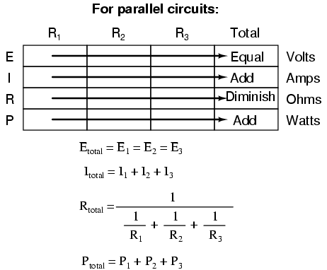
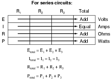
    Kirchhoff's and Ohm's Law apply. If each cell is .002 Ohms with 4 in series is .008 Ohms


    Deriving values horizontally across columns is allowable as per the principles of series and parallel circuits:


    MSEE, PE

    Comment


    • #3
      Originally posted by PNjunction View Post
      I never thought of this problem before - need clarification.. Mostly a mind-thought exercise, so no need to go nuts.

      Does the internal resistance of a single cell ALSO need to include the internal resistance of any cells prior to it?

      I'll start out with a perfect-world scenario:

      I have simple 4S battery, where each cell is exactly equal to each other in both capacity and internal resistance. Let's say cell interlinks are zero, for the sake of argument. Let's say the internal resistance of a single cell is 2 milliohm.

      So, during operation, is it something like this during charge and discharge:

      Cell 1 IR = 2 milliohm
      Cell 2 IR = 4 milliohm (cell 1 and itself)
      Cell 3 IR = 6 milliohm (cell 1, 2, and itself)
      Cell 4 IR = 8 milliohm (cell 1, 2, 3, and itself)

      My mind is reeling. If that is the case, then even bottom-balancing is no guarantee of hitting the same voltage at the same time *in the lab-perfect world*, under discharge. Bottom balancing procedure involves *resting voltages* of individual cells, and not an in-series *discharge / charge voltage*. Maybe it is so small it doesn't matter. I don't have a high-current application, so I haven't seen major differences when bottom-balancing where this kind of IR-differential under working conditions matter, but still wonder, especially with long strings, like one might have with a 48v bank?

      Would the lab-perfect solution be to manufacture each successive cell with different IR values to compensate, or more easily manufacture each cell with a slightly different capacity to compensate for the differences in IR? Of course each cell would have to be positioned properly. This is a thought-question, and not real-world obviously.

      Or am I just thinking outside the box (er, butt most likely.)
      You are verging on a rectocranial inversion, yes.

      The IR for cell 4 is just 2 milliohms. It is the IR of the whole pack that changes with what cell you tap from.
      The result is that each cell's terminal voltage will be that of that one cell plus the IR drop of that one cell.
      Balance is not affected, only the overall voltage set point.

      The moral of the story is that your balancer needs to work based on the voltage between the two terminals of each cell rather than the voltage from a particular cell terminal (tap) to ground.
      (Use an op amp with differential input, for example, or subtract the voltages digitally.)
      SunnyBoy 3000 US, 18 BP Solar 175B panels.

      Comment


      • #4
        Great answers guys - thanks!

        What got me going on this mental exercise is wondering about which leg of a battery circuit is best to monitor current from? I notice differences depending on whether I put my metering (or a shunt) in the positive leg of the battery or the negative leg of the battery circuit for the most accuracy.

        Still wonder which side of the batter (positive leg or negative leg) is the one I should really be counting/measuring from depending on if I'm charging or discharging?

        While not practical, it almost makes me think I might want to switch positions of the current meter depending on charge or discharge for that kind of crazy accuracy....
        Last edited by PNjunction; 12-19-2016, 04:41 AM.

        Comment


        • #5
          Originally posted by PNjunction View Post
          Great answers guys - thanks!

          What got me going on this mental exercise is wondering about which leg of a battery circuit is best to monitor current from? I notice differences depending on whether I put my metering (or a shunt) in the positive leg of the battery or the negative leg of the battery circuit for the most accuracy.

          Still wonder which side of the batter (positive leg or negative leg) is the one I should really be counting/measuring from depending on if I'm charging or discharging?

          While not practical, it almost makes me think I might want to switch positions of the current meter depending on charge or discharge for that kind of crazy accuracy....
          If you are using your multimeter to measure the voltage across the shunt to determine the current it shouldn't make any difference which terminal you have the shunt on. On the other hand if you are using a current meter that gets its power from the battery you need to have the shunt on the negative terminal. If the shunt is on the positive terminal it is likely that the op-amp that measures the current and converts it to a form that can be displayed will be operating outside its operating voltage range and/or the voltage on the plus terminal of the battery will cause a voltage offset in the op-amp which will be interpreted as current. Google CMRR (Common Mode Rejection Ratio) for more information.

          To measure charge and discharge current with the same meter you will need a meter that can measure current going in both directions. To do this the op-amp that measures the current within the meter will have to work with both negative and positive voltages up to the maximum voltage across the shunt.

          Simon

          Off grid 24V system, 6x190W Solar Panels, 32x90ah Winston LiFeYPO4 batteries installed April 2013
          BMS - Homemade Battery logger github.com/simat/BatteryMonitor
          Latronics 4kW Inverter, homemade MPPT controller
          Last edited by karrak; 12-19-2016, 09:55 AM. Reason: added last paragraph
          Off-Grid LFP(LiFePO4) system since April 2013

          Comment


          • #6
            PN all wires and connections have resistance. If you take a reading through them, they are included. Obtaining a realistic Ri of batteries is not real practical, and the only possible way to have any meaningful reading is using Delta Voltage Delta Current. Although your hobby charger like a PL8 does a very poor job of measuring and can only be used as a base reference point as there is no real accuracy involved.

            The only way to get an accurate result is to take the string apart, remover all wiring and connectors, then use delta voltage/current measurement right on the battery term post. Issue is if you do not know what a good reading is to start with is not of much use except spotting a defective cell.

            In the good ole days pros tested batteries via Capacity Test. That is very expensive and time consuming. Imagine testing a 40,000 AH battery with a constant current 1000 amp load box. Real exciting profession. Like watching paint dry for a living. Some companies still do that with large FLA batteries, but today most pros use a Midtronics Battery Conductance meter. When the batteries are new and fully charged, each cell Conductance is measured and recorded as the Reference Baseline. Then once a month/year you measure Conductance and compare it to previous readings. When you note the Conductance going down, time to write a check and buy new batteries. There is a relationship between Conductance and Capacity. When Mho's go from say 8000 Mho's to 4000 Mho's, you rbatery is at 80% capacity and just a matter of short time before they are done. Once a battery starts to loose capacity, it is a very fast ride down to zero.

            So to use Ri or Conductance you need to know what is good to start with by taking a Baseline Reference. Otherwise it is just WAG if using to determine battery health
            Last edited by Sunking; 12-19-2016, 01:33 PM.
            MSEE, PE

            Comment

            Working...
            X