Announcement

Collapse
No announcement yet.

Constant Current Discharge Ratings - Can I simply multiply x 4?

Collapse
X
 
  • Filter
  • Time
  • Show
Clear All
new posts

  • Constant Current Discharge Ratings - Can I simply multiply x 4?

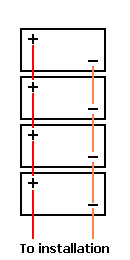
    I am using a 4 pack of 35 Amp 12 volt AGM Interstate DCM-0035 AGM batteries as a "transportable" power bank. These are wired in Parallel to provide 140 amps (theorhetical) of 12 volt power.

    The DCM-0035 battery ia advertised as a "VALVE-REGULATED LEAD-ACID BATTERY FOR DEEP-CYCLE APPLICATIONS". They weigh 23.1 pounds each and come with a top carry strap. This makes them transportable by hand (67 years old = two trips).

    I have a very detailed chart of
    Constant Current Discharge Ratings supplied with the battery.

    By the chart it shows that a single DCM-0035 can supply 3.6 amps for 8 hours with an end point of 10.8 volts. For planning could I project that 4 DCM-0035 batteries in parallel could supply 3.6 amps for 32 hours and end at the same 10.8 volts. (4 x the 8 hours).

    I guess I am asking if each battery would "contribute" equally to supply the total amp output (3.6 amps/4). If so, then I can use the Constant Current Discharge Ratings chart supplied.

    Thanks in advance for any guidance and/or advice.
    rch
    Last edited by rhouser; 09-22-2017, 10:55 AM.

  • #2
    If you wire those batteries in parallel the chances of any "equal" discharge or charging would be rare due to the uneven resistance paths. In the end one or two of those 4 will take the brunt of the load and die off quicker then the other two.

    Also discharging any 12volt battery to 10.8v is a death sentence. You really should never go below 12volt since they usually start at approximately 12.8v at 100% SOC.

    Comment


    • #3
      rhouser,

      Yes, you can "simply multiply by four", but ...

      I would never ever drain those batteries down to 10.8 volts.
      10.8 volts is an early death.
      The reason is ... you will not get very many cycles if you continue do this.

      I would draw 2 amps for 8 hours ( 50% max ) from each battery.
      That would allow your load to draw 2 amps for 32 hours with 4 batteries in parallel.

      Look at Smart Gauge for "opposite diagonal parallel battery wiring" ...
      http://www.smartgauge.co.uk/batt_con.html

      How many charge / discharge cycles do you need for your project ?

      The deeper you discharge these batteries, the fewer the cycles.
      Last edited by NEOH; 09-22-2017, 01:18 PM.

      Comment


      • #4
        Originally posted by SunEagle View Post
        If you wire those batteries in parallel the chances of any "equal" discharge or charging would be rare due to the uneven resistance paths. In the end one or two of those 4 will take the brunt of the load and die off quicker then the other two.
        I think this depends on degree of the original imbalance. If it is fraction of battery internal resistance then minimal degradation of the more loaded battery would balance paths but if on 2 mOhm batteries the difference is also 2mOhm more loaded one would be practically killed before balancing point.

        Comment


        • #5
          If you do have to wire four or more batteries in parallel, you would be well advised to read the technical tips at http://smartgauge.co.uk/batt_con.html and surrounding pages.
          SunnyBoy 3000 US, 18 BP Solar 175B panels.

          Comment


          • #6
            Thanks to all who replied:

            I am using the "opposite diagonal parallel battery wiring" as diagrammed on http://www.smartgauge.co.uk/batt_con.html.

            For cabling, I use 2 - commercial 6" 4ga ring terminal cables for each battery set "pairing" and 2 - commercial 12" 4ga ring terminal cables for tying the 2 pairs IAW the "opposite diagonal parallel battery wiring" diagram. For output, I am using 2 - 18" 2ga ring terminal cables to run from the battery pack to my inverter. I believe I have done everything possible on the "load balancing side".

            The 10.8 volt discharge figure was used for the math problem. I pulled the amps and hours from my discharge rate chart. I was looking for opinions on whether I could multiply the listed time x 4 (number of batteries in the set) and expect the actual performance to be close to the published figure.

            Neoh gave me a qualified yes.

            again, thanks to all
            rch
            Last edited by rhouser; 09-23-2017, 08:58 AM.

            Comment


            • #7
              Originally posted by rhouser View Post
              Neoh gave me a qualified yes.
              But SunEagle gave the better answer. AGM internal resistance is low, so differences in either internal or external resistance will more significantly affect the current flow (as max2k was getting at). You should plan to verify the balancing by measuring current from each individual battery and adjust as needed to keep them close. The problem is that they won't necessarily stay equal over time, so you'll have to watch it if you don't want to be replacing the pack in a year.

              Furthermore, capacity is a function of discharge rate (puekert), so if you can run 3.6 amps for 8 hours from one battery, you'd get longer than 32 hours from four in parallel because you've dropped your discharge rate as a fraction of capacity. The effect is smaller for AGM than FLA, and you probably won't achieve it because of imbalance, but that is at least the ideal result for your math problem.
              Last edited by sensij; 09-23-2017, 10:42 AM.
              CS6P-260P/SE3000 - http://tiny.cc/ed5ozx

              Comment


              • #8
                Sensij, thank you for introducing an additional factor that I have been thinking about. Hypothetically:

                If I were delivering an 17 amp load, I would hit 11.2 volts battery state in 1 hour. If I multiplied the 1 hours x 4, I get 4 hours of 17 amp to an ending battery voltage of 11.2.

                Reading the chart for a delivery rate of 4.25 amps (17 amps / 4 batteries), my chart shows I would get closer to 6.5 hours at the 4.25 amp rate. God bless Puekert.

                I can tag and rotate batteries in the wiring position because it is a SMALL pack that is transported "disassembled" with the cabling in a gallon ziplock bags, the inverter, and the batteries. I just wanted to confirm that I could effectively use the supplied Constant Current Discharge Ratings chart for making on the spot "time of service" estimations for devices "discovered" on station. Example, how long will my pack support this off line oxygen generation device etc.

                I have an additional (final) question: I am using a NOKO Genius 26000 (26 amp) smart charger to maintain the pack. I am using their factory AGM setting to manage the charge cycle. I am setting up the entire pack using the "opposite diagonal parallel battery wiring" and then using the two exit points to attach the charger ring terminals to the battery pack. This seems to work well and is more hands off then charging one at a time.

                Would I be better off to run 4 separate charge cycles (individual batteries) and then join them to let them equalize the charges? My idea was that charging them enbloc would leave them in a balanced state once the float stage was finished. Any advice would be appreciated.

                v/r
                rch

                Comment

                Working...
                X