-
Finally got the trailer cleared out! Now I can start dismantling the inside. -
Here it is July, and it's still raining where I live. But I did get a box built for my battery.
We're still cleaning out the carport so I have room to empty out the trailer. Can't really work on it until it's empty. I'm hoping this week I'll be able to start moving things.
Leave a comment:
-
I don't know if it's too late, but I made a 6x12' conversion like this back in the 90's. We didn't use solar, just some oil lamps. Basically it had a sleeping platform, a couple windows, a gravity shower, and a bunch of storage shelves.
What I did find out is to make a 5" layer (your panels?) on the roof that can lower the cabin temp by 20F. I put a thick silver tarp on top of bolts sticking through the roof into the eyelets, giving about a 5" airspace between the roof and the tarp. Next, I tied-down the edges with bungees. Then I put four screened 6x14"(?) vents in the floor, next to the walls, and matched them in the roof. A lot like your average tent, the tarp protects from the rain.
I kept the vents open during the day, then closed during a cold night. I duct taped the roof vents during traveling if it rained. Sold the thing before working out a better fix, I would probably have made a inner tube cover and dzus fasteners. I'm sure they make flaps of some sort these days. Have fun!Leave a comment:
-
Don't know what's best practices on your system but the 1 thing I needed to do before my home system was certified was to unbolt 1 clamp from every paned and file the anodizing off the panel contact pt and the clamp face to ground every panel. He made me promise to do it and he'd sign me off. So I did it.
I think I did it.
I know I meant to.
I hope I did it
Leave a comment:
-
I'll have to work out the details once I actually start to build the thing. In the meantime, here's an updated diagram based on what I've learned so far:
2618b947f7f177478b57a85a19f7aa11.jpg
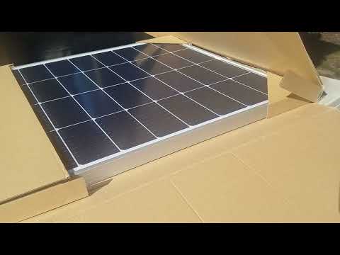
I think that's going to be all for my grounding research. In other news, I got my solar panels! I made a short video of my solar plan and unboxing and testing a few of the panels.
This weekend is the last cargo run before the trailer gets gutted and rebuilt. From there, progress will only be limited by funding, weather, and how much energy I have between this and other projects.Leave a comment:
-
Aluminum should not be counted on for any electrical capacity, unless it's tin plated. It oxidizes instantly, and the oxide layer is a super tough insulator. (aluminum oxide sandpaper). Look into tin plated copper braid, or route some bare #2 wire as your ground.Leave a comment:
-
Well, I've done more digging around, and I still think that what I know is correct. As for the things I'm not sure of, it's looking like the solar panel frames and any mounting hardware should indeed be grounded to the trailer body. What's more, a lot of aluminum products are anodized, which causes high resistance, so any ground points should be connected to actual bare aluminum. It looks like the ground lug on the inverter body should also be grounded to the trailer body. And from what I've seen, all the ground wires meeting up at the transfer switch should be connected.
I guess there's some inverters that bond the neutral to ground on the AC output side to simulate a path to ground. Some appliances and electronics won't work if they detect an open ground. I think this is what my inverter does. So in my case, I definitely need to have both the hot and neutral wires isolated at the transfer switch. This will prevent having more than one neutral/ground bond in the system at a time.
I've also just learned that there is supposed to be a bond between the AC ground and the DC negative. But only one. When the trailer is hooked up to the truck, The AC ground will be bonded to the truck's negative through the chassis. But that goes away when it's unhitched. My battery is a different voltage than the truck's, so I've been planning on keeping the DC isolated from the AC. Not sure now if that is still the best way to go or not.
Leave a comment:
-
New video:
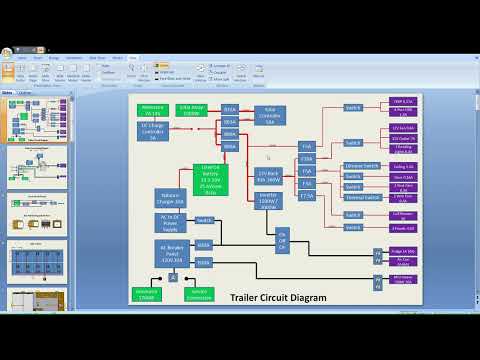
Just me talking again. This time I'm giving a brief overview of how I plan to do the electrical. I've updated my wiring diagram too, based on some new stuff I've learned lately about my battery and solar panels in general.

I've been thinking about grounding lately. Specifically, what to do with the ground wires that lead up to my isolation switch, and the ground post on the body of the inverter. I've made a diagram showing much more detail of the AC side of things to maybe help me figure it out.

So here's what I think I know:
-If the trailer is connected to a service connection somewhere, there should be a physical ground rod buried in the actual dirt somewhere.
-If the trailer is connected to a generator, there should be a bond between the ground and neutral. Either inside the generator or via an adapter.
-If the trailer is connected to nothing, there will be no ground connection to either neutral or earth.
-The neutral bus bar in the breaker panel needs to be isolated from ground.
-The trailer body needs to be connected to ground.
Here's what I'm not sure of:
-The solar panel frames (being aluminum) and mounting hardware should be grounded to the trailer body?
-The solar panel frames should also be grounded to the inverter via the ground connector on the inverter's body?
-The inverter body should be grounded to it's AC output ground?
-All the ground wires meeting up at the isolation switch should be connected together?
Vaguely related: I plan to use GFCI breakers, or maybe the GFCI/AFCI combo breakers.
Anyway, does it mater that sometimes the trailer will be connected to a ground rod, and sometimes just boded to neutral, and sometimes neither?Leave a comment:
-
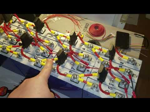
That all makes sense to me. I noticed when I tested all the cells that they settle to around 3.4V after charging to 3.65V. I've wondered if that is normal for LiFePO4. I'm used to working with Li-Ion, and they hardly settle at all. I picked LiFePO4 for this project because it's a more sable chemistry, and the voltage range is more compatible with all the components I want to use. I wonder if it even makes sense to charge them all the way up to 3.65V? I could see that if they settle anyway, trying to keep them topped up might take more energy than what is lost if they're just charged to say, 3.5V or something. I let my cells sit for a few weeks after charging and they never went below about 3.4V.
I've set the BMS balancing for 3.4V for now. My concern is that I don't want the BMS shutting off the battery except in a bad situation. The solar charge controller may take damage if the solar power is connected, but the battery is not. According to the manufacturer anyway. I have already top balanced my cells before connecting the BMS. I just hope the very short balancing time will be enough to keep them in balance. I am hoping to keep the battery above 20% SOC as much as possible. I'm thinking of having the controller only charge the cells to 3.6V. That would keep the battery at 28.8V, and I won't have to worry about the BMS shutting off.
The workaround for the Bluetooth time out seems to be working. I read on the internet that entering 65,535 in the timeout setting disables the Bluetooth timer, and keeps the BMS from shutting off the battery due to inactivity. My concern here is that the solar charge controller won't reactivate the BMS if the BMS has shut of the battery due to inactivity. The charge controller can only function if it already has power from the battery. It won't run on solar at all. The Bluetooth part of the workaround works. Even if the second part doesn't work, that number of seconds is a little over 18 hours, and being on the solar charge controller should be enough to reset the timer by then. If I were to "winterize" the trailer, I can set the timer back to a small number. I think the default was 3,600 seconds.
Anyway, I think this BMS will be fine for the trailer battery. And I love that I can change the settings and monitor what the BMS is doing via a phone app.Leave a comment:
-
For balancing most BMS have a setting to start charging. Also, a separate setting to balance only when charging. Mine is set to only balance when charging and 3.40 volts and greater. My SCC charges at 3.475 per cell.
For my BMS to balance, that’s basically only a few minutes a day after the pack has hit absorption. Lithiums are much shorter with the absorption cycle. Also, the cells settle after charged. I forget mine, but it’s less than 3.4.
Top balancing cells prior to install is important. If you did not, the BMS would take weeks or months.
Theres a whole debate over whether adding active balancers are worth it.
My opinion is if that balancer is balancing all the time and your cells spend most of the time below a full SOC, than it could throw the top balance off. This is someone who gets his batteries to 20% every night.
After reading that I was happy with the BMS balancing only after 3.4 volts.
If you only use these batteries a few days a month and the rest of the time they’re fully charged, than a active balancer could good.
Leave a comment:
-
My BMS has arrived! It's a Daly 8s 80A. It's my first "smart" BMS, so there has been quite the learning curve. I can monitor and change settings over Bluetooth, which is great. However, the app is in poorly translated english, and it's been difficult finding specific information and explanations about the settings. I think I'm getting it figured out though.
Apparently there are better BMSs out there that have similar features, but I wasn't aware of them at the time I bought this. It may work for the trailer battery, but it's got a couple characteristics that I'm not liking.
First, it has a "time out" feature, where if no current is going into or out of the battery for a settable amount of time, the BMS will not only shut off the Bluetooth, but also the whole battery connection. It wakes up when there is a lode or charge put on it, but in the case of a solar battery that could be potentially problematic. See, without power to the charge controller, the solar power can't get to the BMS to wake it up. However, you can put a very long amount of time into the setting so it won't go to sleep overnight.
The Bluetooth connection seems to be on an independent timer though. It will shut off after a minute or so of no battery current regardless of the timer setting. I've seen suggestions for a workaround, so I'll try that. But otherwise, you have to push the little button on the Bluetooth dongle or make sure the battery is experiencing some kind of current. The tiny amount of current needed to run the solar charge controller doesn't seem to be enough.
The second issue, is that the Daly seems pretty picky as to the conditions that need to be met before it will balance the cells. The minimum cell voltage can be set, as well as the voltage difference between the highest and lowest cells. Those are two of the conditions. The third though, is that balancing will only occur if the battery is being charged by a certain amount of current. Like an Amp or so, but I'm not sure. Also, balance current is limited to 30mA. Doesn't seem like enough to balance large capacity cells.
Good news is that it seems easy enough to physically hook up to the battery.

The battery is still only temporarily put together. I'm expecting more parts in the mail tomorrow.

More good news; the BMS seems to be measuring the voltage and current pretty accurately.

I finally got the whole battery down to about 22V, so I could test the behavior of the solar charge controller. It still only needs about 2.2V difference to charge the battery. I'm glad I got the BMS when I did though, as the cells are getting quite out of balance as they approach their bottom voltage. I'm charging the whole battery back up now, and I'll see what the balance looks like back at the top.
I wonder if they have different internal resistances. I may try to measure that. They all have the same capacity though, and behaved the same during the discharge test. Anyway, back to tinkering...Leave a comment:
-
Well I bit the bullet as they say, and bought the solar panels. painful on the wallet, but this way I can be sure they all match. Final bill was $1,034.49 after tax. Shipping is free. so about $1.04 per Watt. As far as I can tell, that's pretty good for smaller panels.
I've been running my old mini fridge for almost a day from the battery and inverter. The battery voltage has barely moved. It may be a couple days before the battery gets low enough to test the charge controller again. I figure that's a good problem to have.
I've made the first video of my series for this project. It's not much; just an introduction. But if anyone is really bored, you can watch it:
0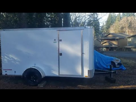
Leave a comment:
-
Yep, that is kind of what I had in mind. Right now I'm thinking inline fuses on the branch connectors, and a breaker to separate the whole array from the charge controller. I plan to have some other breakers in the system too, so I can put them all together on a DIN rail.
Unfortunately, I haven't been able to find anything cheaper locally. The panels I'm looking at are $95 each, or $0.95 per Watt. All the bigger panels I could find are $1.25 per Watt or higher. Also, their shape won't allow me to fit 1,000W worth on the roof. It's like playing 4 dimensional Tetris. Hight, width, price, Watts. Finding the right combination has been a bit of a brain buster, LOL.Leave a comment:
-
The easiest way for inline fuses is to buy branch connectors and the fuse attachment for those. 5P2S is difficult in finding a branch connector. A combiner box would work and you could put circuit breakers in versus fusing. Circuit breakers are a bit more expensive but can shut the panels off prior to powering down the system. Also helps in troubleshooting.
Five fuses or circuit breakers are needed.
Don’t know if its been discussed, but you could save a bit of cash by buying larger panels. Locally, there’s usually a dozen panels for sale new or used at much cheaper prices than 100 watt panels. Also, I can locally purchase from San Tan Solar and pick those up in my truck.Leave a comment:
-
Looks like I may have enough money to finally buy the solar panels. This has renewed my interest in figuring out exactly how to wire them up. I'm still a noob at solar, but I've watched a lot of videos, and done a lot of reading. I think I have a viable plan:

Took a while, but it finally dawned on me that a "12V" solar panel has nothing to do with 12V. The numbers in the diagram are rounded somewhat for simplicity. These particular panels happen to be the perfect shape to cover the whole roof. Vents and other traditional roof things will be on the sides of the trailer. I've never heard anyone complain of having too much solar, so I decided to take advantage of the whole space.
Here are the specs for the panels I found:

Hopefully the diagram makes sense. The idea is to have 5 sets of 2 panels in series, and then connect those 5 sets in parallel. This setup will need a 5-into-1 pair of connectors, and I think a 10 or 12 AWG cable to connect it to the charge controller. The controller I bought recommends a breaker between the panels and the controller. I'm looking into the din rail style ones.
I've also read that inline fuses are sometimes needed to protect the panels from themselves if one gets a short circuit. Makes sense. We fuse our individual battery cells on the bus bars, so a similar concept for solar panels. Not sure if I need any fuses in this case, but I'm thinking 10 or 15A fuses on each series, so that if one series goes nuts, the others can't just dump power into it.
Anyway, have I missed anything?Leave a comment:


Working...
😀
😂
🥰
😘
🤢
😎
😞
😡
👍
👎
☕
Leave a comment: