Announcement

Collapse
No announcement yet.

Help sizing wires/fuses

Collapse
X
 
  • Filter
  • Time
  • Show
Clear All
new posts

  • Help sizing wires/fuses


    Running a 24v battery bank with 2/0 wire.
    What size fuse on the battery terminal going to the bus bar?
    What size fuse between the bus bar and charge controller? 2/0 wire
    What size fuse/wire between the bus bar and down converter?
    this is a little strange because i believe the down converter is only 30 amp
    Anything else i am missing, or that is wrong?

    Thanks so much for the help.
    dave


    Solar.png
  • #2
    Originally posted by MambaJack View Post

    Running a 24v battery bank with 2/0 wire.
    What size fuse on the battery terminal going to the bus bar?
    What size fuse between the bus bar and charge controller? 2/0 wire
    What size fuse/wire between the bus bar and down converter?
    this is a little strange because i believe the down converter is only 30 amp
    Anything else i am missing, or that is wrong?

    Thanks so much for the help.
    dave


    Solar.png
    You could do 2 strings of 3 instead of 3 strings of 2 and save yourself a fuse box for the panels. You also don't need a breaker on the PV side since the panels are current limiting. It's physically impossible for 2 or 3 strings of panels to exceed 40A so that breaker will never do anything other than function as a switch.

    Also; Why did you choose 24v instead of 48v?

    Comment


    • #3
      Cool thx. Got a recommendation on here to go 24 quite a while back. I did add some panels and a bigger controller since then since got a good deal on them

      Comment


      • #4
        Originally posted by MambaJack View Post
        Cool thx. Got a recommendation on here to go 24 quite a while back. I did add some panels and a bigger controller since then since got a good deal on them
        The main reason to go 24v vs 48v is usually to buy fewer batteries but since you're already getting (8) 6v batteries I can't think of any benefit to 24v. With 24v you're doubling your current so all your wires need to be bigger and your line losses are higher. Loss loss is current squared so doubling current increases line loss 4x for the same wire.

        I personally prefer breakers to fuses. The breaker from battery to the bus bar should be 100A if 24v or 60A if 48v. You'll have to check the manual for the charge controller to determine the over current protection it requires but I think the battery breaker (50A) would be sufficient for a 48v system but 100A may be too much so you may need another breaker for 24v. If you have a fault anywhere the battery breaker would trip and open the circuit. With a 24v system each battery bank will require a separate OCPD.

        Comment


        • #5
          That is excellent. Thanks so much for the help. As far as 24 vs 48. I unfortunately already own the inverter charger and it is 24v.

          Comment


          • #6
            Originally posted by nwdiver View Post

            With a 24v system each battery bank will require a separate OCPD.
            Thanks! I had purchased a MRBF terminal fuse block kit. does this mean i need 2 of them then? one for each string of batteries connected together?

            Comment


            • #7
              Originally posted by nwdiver View Post

              The breaker from battery to the bus bar should be 100A if 24v
              Also, will this cause a problem with my current inverter, 2000w, 6000w surge.
              When i purchased it, i was told to put a 150 amp fuse inline from the 24v bank?

              One of the reasons i was using 00 wire was to allow for a little more amperage

              Thanks,
              dave

              Comment


              • #8
                Originally posted by MambaJack View Post

                Thanks! I had purchased a MRBF terminal fuse block kit. does this mean i need 2 of them then? one for each string of batteries connected together?
                Yes. Each battery bank should have it's own breaker. You could put a 75A breaker on each. You don't need a combined breaker provided all wire upstream of the breaker is able to handle the combined 150A.

                I have a similar setup except 48v instead of 24. I have 2 48v battery banks and each bank has a 100A breaker. My charge controller has a 64A breaker on the 48V side to protect it from the battery amperage in case of a fault. There is no OCPD on the PV side since the panels are current limiting and I only have 1 string.
                Last edited by nwdiver; 09-10-2019, 03:38 PM.

                Comment


                • #9
                  In your shoes, I'd up the wire size to 3/0, and use a 200A fuse on each battery string, to the bus bar, and then use the wire size and fuses needed to your circuits from the bus bar.
                  Your battery interconnects should also be 3/0. If one string of batteries dies for some reason, the 2nd string would be able to handle the load till replacements/repair is accomplished
                  If you stay with 2/0, scale the fuse down to the proper size

                  I'd also suggest simply using 3, DC rated breakers at your PV combiner box. I question the 20A fuse on the PV panel strings, I think 15A would be closer to the Series Fuse spec on the panel.
                  The breaker on the combined ( - ) cable is generally not needed.

                  I'd use the 4 space in the combiner panel, as a spot to locate a breaker for the Controller-Battery connection, you really want a switch rated breaker there, as part of updating firmware and troubleshooting the Controller, is a power off - Reboot. Can't do that with a fuse, most holders, while "touch safe" are not rated to interrupt the circuit.

                  Combiner http://www.midnitesolar.com/productP...tOrder=5&act=p
                  Breakers http://www.midnitesolar.com/productP...tOrder=1&act=p
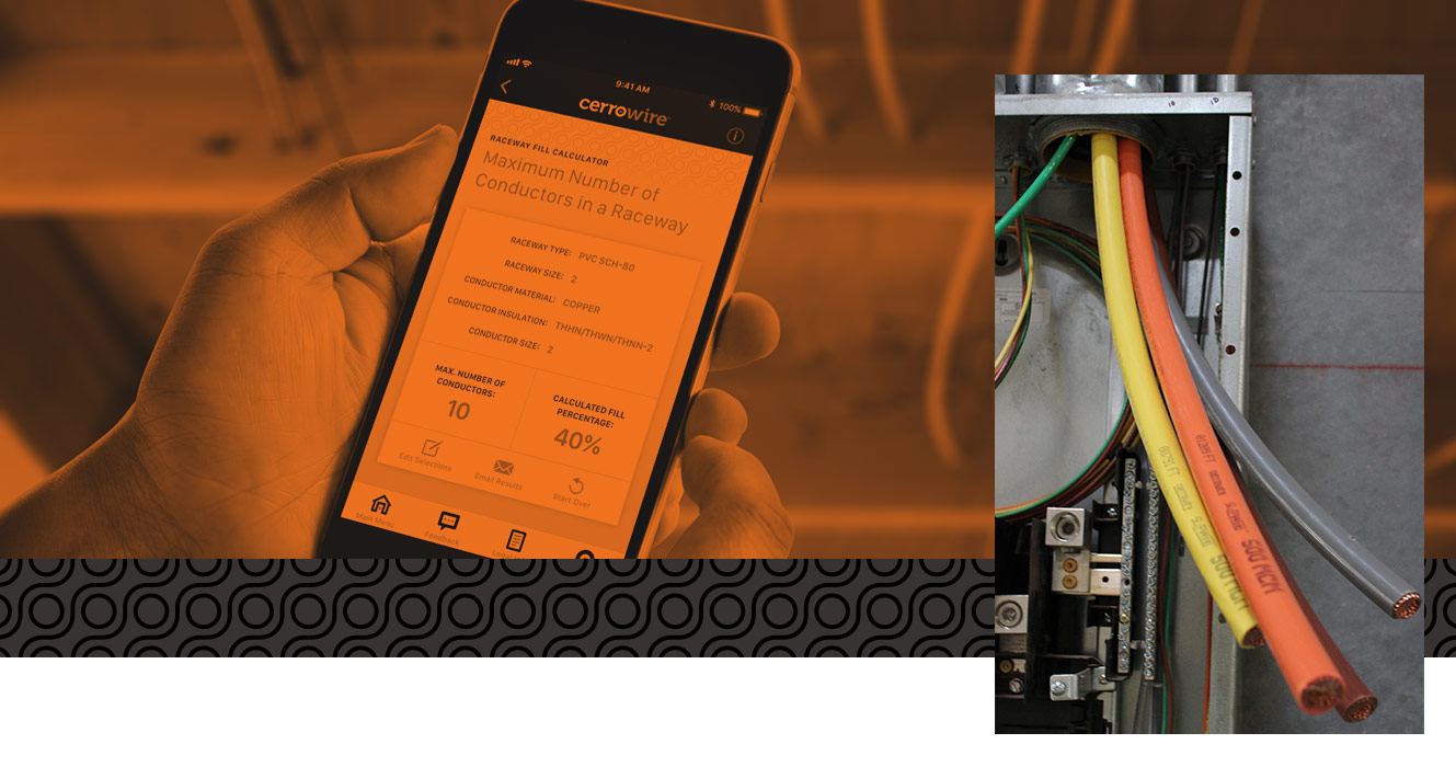
                  https://www.cerrowire.com/products/r...pacity-charts/


                  20160821_132247cc.jpg
                  Powerfab top of pole PV mount (2) | Listeroid 6/1 w/st5 gen head | XW6048 inverter/chgr | Iota 48V/15A charger | Morningstar 60A MPPT | 48V, 800A NiFe Battery (in series)| 15, Evergreen 205w "12V" PV array on pole | Midnight ePanel | Grundfos 10 SO5-9 with 3 wire Franklin Electric motor (1/2hp 240V 1ph ) on a timer for 3 hr noontime run - Runs off PV ||
                  || Midnight Classic 200 | 10, Evergreen 200w in a 160VOC array ||
                  || VEC1093 12V Charger | Maha C401 aa/aaa Charger | SureSine | Sunsaver MPPT 15A

                  solar: http://tinyurl.com/LMR-Solar
                  gen: http://tinyurl.com/LMR-Lister

                  Comment


                  • #10
                    Originally posted by Mike90250 View Post

                    I'd also suggest simply using 3, DC rated breakers at your PV combiner box.
                    Why not just do 2 strings of 3 and delete the fuses or breakers?

                    Also just noticed. I think the 63A breaker is in the wrong position. Should be on the Batt side not the PV side. OCPDs on the PV side is for protecting the panels not the charge controller. The charge controller is generally protected from over-current by properly sizing the array.
                    Last edited by nwdiver; 09-10-2019, 07:12 PM.

                    Comment


                    • #11
                      Originally posted by nwdiver View Post

                      Why not just do 2 strings of 3 and delete the fuses or breakers?
                      ......
                      Because:
                      1) Running a higher voltage means more losses (heat) in the charge controller
                      2) Having a disconnect for each PV string, means being able to trouble shoot any problem within 90 seconds to one string.

                      You also have to be able to easily disconnect the PV array from the controller for any power cycle reboot sequence, you can't have 90V pf PV feeding into a MPPT charge controller with no battery attached.
                      Powerfab top of pole PV mount (2) | Listeroid 6/1 w/st5 gen head | XW6048 inverter/chgr | Iota 48V/15A charger | Morningstar 60A MPPT | 48V, 800A NiFe Battery (in series)| 15, Evergreen 205w "12V" PV array on pole | Midnight ePanel | Grundfos 10 SO5-9 with 3 wire Franklin Electric motor (1/2hp 240V 1ph ) on a timer for 3 hr noontime run - Runs off PV ||
                      || Midnight Classic 200 | 10, Evergreen 200w in a 160VOC array ||
                      || VEC1093 12V Charger | Maha C401 aa/aaa Charger | SureSine | Sunsaver MPPT 15A

                      solar: http://tinyurl.com/LMR-Solar
                      gen: http://tinyurl.com/LMR-Lister

                      Comment


                      • #12
                        Originally posted by Mike90250 View Post

                        Because:
                        1) Running a higher voltage means more losses (heat) in the charge controller
                        2) Having a disconnect for each PV string, means being able to trouble shoot any problem within 90 seconds to one string.

                        You also have to be able to easily disconnect the PV array from the controller for any power cycle reboot sequence, you can't have 90V pf PV feeding into a MPPT charge controller with no battery attached.
                        I would argue that the cost of a combiner box doesn't justify that benefit. What would the loss increase be? 2%? The added cost would be >$100.

                        To each his own I suppose but I prefer to reduce the number of components as much as possible. If I can configure a system without a combiner box or fuses that's what I do.
                        Last edited by nwdiver; 09-11-2019, 02:41 AM.

                        Comment


                        • #13
                          Originally posted by Mike90250 View Post

                          Because:
                          1) Running a higher voltage means more losses (heat) in the charge controller
                          2) Having a disconnect for each PV string, means being able to trouble shoot any problem within 90 seconds to one string.

                          You also have to be able to easily disconnect the PV array from the controller for any power cycle reboot sequence, you can't have 90V pf PV feeding into a MPPT charge controller with no battery attached.
                          My plan was to use 2 63 amp breakers, one between the charge controller and the batteries and one between the charge controller and the panels. mainly to be able to switch them off if i need to.

                          Also, because of cost I hadn't planned to use a combiner box, rather inline fuse each pv wire and run them all directly into one side of the breaker.
                          I setup part of it last night and will take a picture.

                          How do people commonly handle the issue with high voltage coming into the charge controller and batteries bank switched off, or what happens if the say the fuse on my bank blows for some reason?

                          Comment


                          • #14
                            The problem with fuses, is that you cannot disconnect or turn them off. pulling a fuse on a live system will cause a DC arc and damage the fuse contacts. ( many arc welders are in the 20 - 40VDC region )

                            That's why i like the combiner box. I can fit my PV breakers and charge controller breakers in it. The midnight breakers are switch rated, so you have a couple thousand cycles before you have to worry about wearing something out. Monthly, I run a test, and go through my strings, looking for one that's different. i switch 2 strings off, record what 1 string performance is, and then compare the others to it.

                            I oversize the cable from battery to controller and use a breaker sized to handle the expected PV output. if there is a catastrophic fault in the controller, the breaker pops and all is well, except for the now dud controller.

                            Sure, automotive maxi fuses are cheaper and you save $, but you do so at the expense of flexibility and troubleshooting. I've been in electronics for 40+ years and never found flexible and easy to be a hindrance. Spending the extra $150 for the good stuff has years of ease as a payback.

                            As to the last case, if a fault occurs in the controller, that's about the only way it's going to overload the battery cable. I'll assume it's toast, and needs replacing, no other reason for it to trip a breaker.
                            Powerfab top of pole PV mount (2) | Listeroid 6/1 w/st5 gen head | XW6048 inverter/chgr | Iota 48V/15A charger | Morningstar 60A MPPT | 48V, 800A NiFe Battery (in series)| 15, Evergreen 205w "12V" PV array on pole | Midnight ePanel | Grundfos 10 SO5-9 with 3 wire Franklin Electric motor (1/2hp 240V 1ph ) on a timer for 3 hr noontime run - Runs off PV ||
                            || Midnight Classic 200 | 10, Evergreen 200w in a 160VOC array ||
                            || VEC1093 12V Charger | Maha C401 aa/aaa Charger | SureSine | Sunsaver MPPT 15A

                            solar: http://tinyurl.com/LMR-Solar
                            gen: http://tinyurl.com/LMR-Lister

                            Comment


                            • #15
                              Originally posted by Mike90250 View Post

                              I oversize the cable from battery to controller and use a breaker sized to handle the expected PV output. if there is a catastrophic fault in the controller, the breaker pops and all is well, except for the now dud controller.
                              With 2 PV strings PV side breakers have no over-current function. Isc and Impp are too close. It's impossible to have a fault that would trip the PV breaker that also wouldn't trip under normal operation. A DC disconnect would be cheaper and more effective.

                              Comment

                              Working...
                              X