
 Tweet
Tweet
Ok so to start, this is my first DIY panel and I'm doing it the old fashioned way with treated plywood and pegboard. I know about EVA and everything, but I'm just making this for learning purposes and for fun.
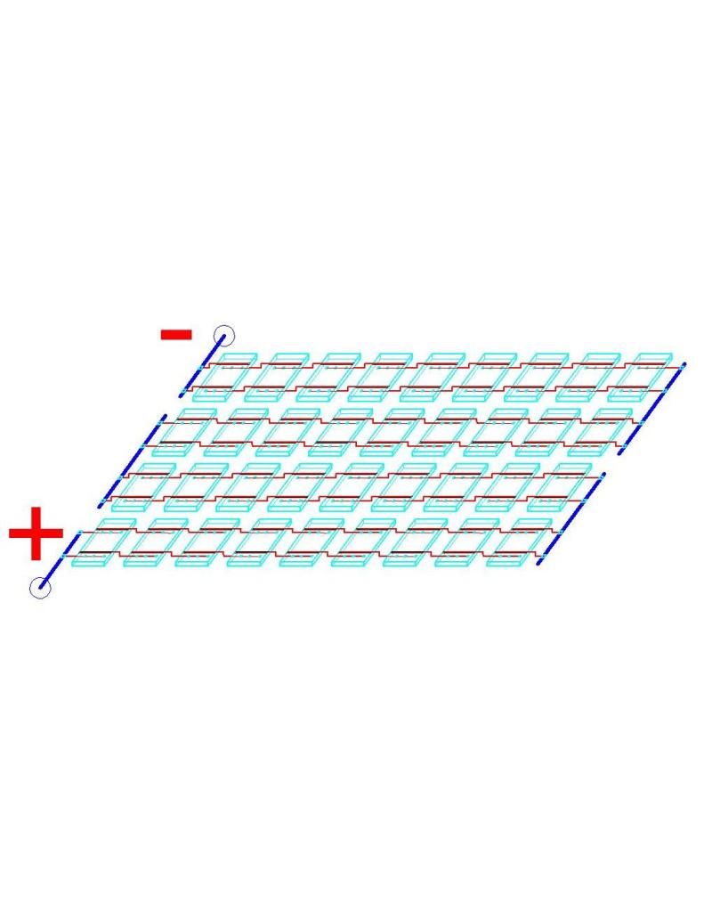
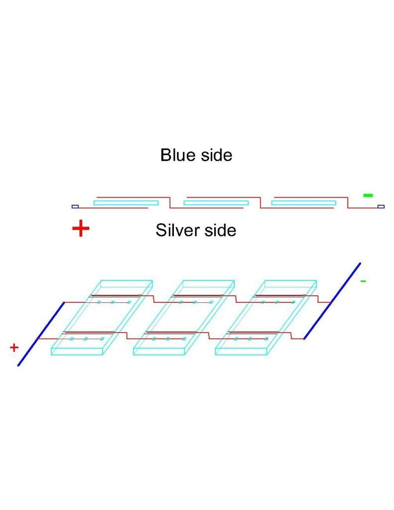
After finally finishing tabbing all of my cells, I began to connect the bus wire to them and noticed that after checking with my multimeter, the voltage was being subtracted as I went from one column to the next. I soon realized that I had tabbed all of my wires the same way, possibly leaving me to make a mistake. I tabbed the positive side first (back side) and then connected that to the negative of the next cell and so on. I made 3 columns of 13. I know typically people make 12x3, but I had a good amount of extras and figured I would tack on 1 more row since I had some room (this may be mistake #1, please let me know). All 3 columns were tabbed the same way, and when it came down to adding the bus wire, I added an extra piece of tabbing wire to the negative side of the top cells on the first row in order to attach to the bus. Here is where I noticed my problem. The picture below will be able to explain my problem.
I realized the error I had made because in the transition to the next column, it was going from positive to positive I believe, so I cut the tabbing wire and attached it to the top (negative side) of the middle column on the last row. I apologize if I'm not explaining this correctly. Before I do anything drastic (because I have already glued it down to the pegboard using silicone; I know dumb move...) I want to know what my next step should be.
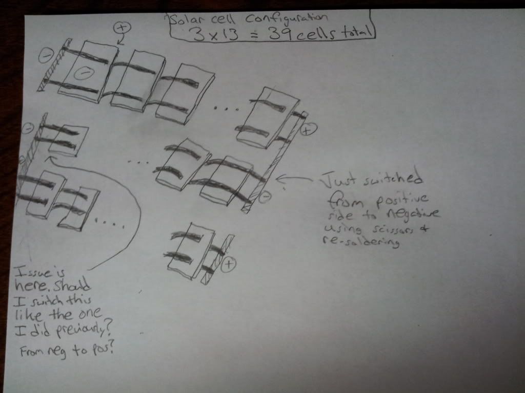
I was about to cut the tabbing wire (as shown in the picture) on the top middle and try and solder it to the bottom (might have to break that cell since its stuck on there), but I'm starting to think the smart solution was to completely flip that middle column around.
I dont understand why I'm making this so difficult. It's a simple series ughh... PLEASE HELP! can't proceed without you. Many thanks
After finally finishing tabbing all of my cells, I began to connect the bus wire to them and noticed that after checking with my multimeter, the voltage was being subtracted as I went from one column to the next. I soon realized that I had tabbed all of my wires the same way, possibly leaving me to make a mistake. I tabbed the positive side first (back side) and then connected that to the negative of the next cell and so on. I made 3 columns of 13. I know typically people make 12x3, but I had a good amount of extras and figured I would tack on 1 more row since I had some room (this may be mistake #1, please let me know). All 3 columns were tabbed the same way, and when it came down to adding the bus wire, I added an extra piece of tabbing wire to the negative side of the top cells on the first row in order to attach to the bus. Here is where I noticed my problem. The picture below will be able to explain my problem.
I realized the error I had made because in the transition to the next column, it was going from positive to positive I believe, so I cut the tabbing wire and attached it to the top (negative side) of the middle column on the last row. I apologize if I'm not explaining this correctly. Before I do anything drastic (because I have already glued it down to the pegboard using silicone; I know dumb move...) I want to know what my next step should be.
I was about to cut the tabbing wire (as shown in the picture) on the top middle and try and solder it to the bottom (might have to break that cell since its stuck on there), but I'm starting to think the smart solution was to completely flip that middle column around.
I dont understand why I'm making this so difficult. It's a simple series ughh... PLEASE HELP! can't proceed without you. Many thanks

Comment