-
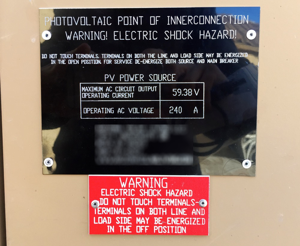
The installer...err I should say...his kids? Literally a couple high schoolers, came out to put on the two missing labels that we needed.
Apparently they didn't know how to rivet the sign on the disconnect because they just double side taped it on there. They were actually on the phone with the installer who said to just tape it and he'll come back out after the inspection to secure it. WTF.
Oh, and the red tag, is supposed to say the DC conductors are ungrounded, not UNDERGROUND. SMH.

The other label they got right, and even riveted it. I think I should black out his info though, he's getting no free advertising from me...or any credit for how the job came out looking in the end.
Leave a comment:
-
I feel like that's really splitting hairs now. I mean installers a lot of times don't even use one of these pre-assembled boxes like I used...they build their use a generic outdoor box and fuses I side.
yeah, not sure why my inverter only has a DC disconnect. As for the permit, if you notice, it has two AC disconnects and my installer only put in one...that maybe be the bigger issue. I think the permit designer figured one disconnect one one side of the tense and one on the other...but the inverter was originally supposed to be inside the garage so maybe that's why my installer didn't put one in since there is a disconnect literally like 8 ft away.Also, your permit called out the SolarEdge inverter with the integral AC/DC safety switch, and yours has only the DC switch. You've got AC disconnects that make it compliant, but it is just another thing the inspector could pick on if he gets the vibe this job was not done right. I'd really roll out the red carpet for the guy.Leave a comment:
-
Where are you going to put those fuses? If it is inside the existing combiner box, then it is a modification to that box. If it is in a different box, then yeah, that could be ok.
Regarding the fuse size, it does look like 20 A would be justifiable. Your permit probably got approved on the basis of 10 panel strings with an Isc of 9.08 AMP, which isn't really correct in a SolarEdge system, but whatever. With 16 * 310 W panels in a string, the rated current for that circuit would be 4960 W / 350 V = 14.2 A, which would require 20 A fuses min. Your 13 panel string would be 4030 W / 350 V = 11.5 A * 1.25 = 14.4 A, so 15 A fuses looks OK for those. The 11 panel string could be sized with 15 A fuses as well.
Also, your permit called out the SolarEdge inverter with the integral AC/DC safety switch, and yours has only the DC switch. You've got AC disconnects that make it compliant, but it is just another thing the inspector could pick on if he gets the vibe this job was not done right. I'd really roll out the red carpet for the guy.Leave a comment:
-
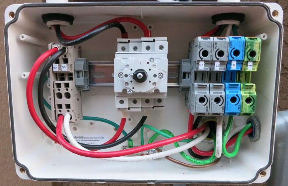
That is strange, I don't know why the wires go from black to red and red to black in the middle terminal block. It came pre-wired from SolarEdge like that.
As for using a white wire for the DC-...well, that's my installer for you...I guess he didn't have black 6AWG wire to use? Guess we'll see what the inspection says, if they even open the disconnect. It would REALLY suck if they say it needs to be changed.
As for the combiner box, I'm not saying to make changes to the box itself...I'm saying to basically just put a fuse between the DC- coming in from the string and the DC- terminal block...I mean isn't that all it is? Isn't that the only difference between the DC+ and DC- setup right now?Leave a comment:
-
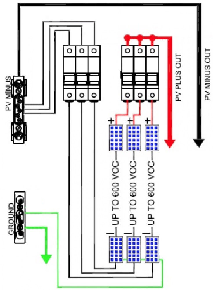
The grounding in the safety switch looks ok to me. The DC wiring, on the other hand, looks off. Firstly, a white DC- wire shouldn't pass inspection. 2nd, what's with the color change of red to black and black to red going through the switch? You aren't in the same terminals shown in the manual, although maybe there is continuity that makes it ok. I know you've been producing power so it must be right, but it doesn't look it to me.
For reference, here is the picture from the manual:
Modifying the combiner box as you suggested is probably not OK. One of the things about code is that all components used must be UL listed for that purpose. Making changes to the combiner box, even if you do everything right and use a listed fuse block, might still not be compliant. Like many things electrical... it will work, but it isn't right. It would be better to do that than leave it as-is, though.
The problem with your AC disconnect ground isn't so much the ground screw, but the way you put more than one conductor in the conduit bushing. If that lug was only listed for one conductor, putting two in it isn't compliant. A clean solution would be to get rid of that extra solid conductor pigtail, and instead cut and strip the green ground wire in the loop so that you have two ends. Those ends could both be grounded to the enclosure using something like this.Leave a comment:
-
-
I don't know if someone else already commented on this - I would scrape a bit more paint off than is shown in the picture a few pages back - so the lug surface area in completely in contact with bare metal. Looks like this job is finally coming to reality - quite a saga. Congrats.Leave a comment:
-
Something else I noticed on an earlier picture concerning the Meter Box. The original installer ran that conduit from the left side which was removed. You will need some type of plug to make it weather tight.Leave a comment:
-
He connected it to the grounding terminal inside the inverter's disconnect box, is this method ok?
I asked the guy at Home Depot for a grounding lug, he gave me a baggie of green grounding screws and said that's what I need.
Would a copper one be good, like this one on Amazon?
http://www.amazon.com/Panduit-CS70-1.../dp/B00B5WAH2SLeave a comment:
-
It won't fail inspection because the inspector does not go on the roof here, so he won't even see it.
I would like it done right though, and I should have bought the specified Sunny Boxy SBCBTL6-10 combiner instead of the one I did, I only got the one I did because it was 1/2 the size and was pre-wired (I liked the MC4 connectors on there, thought it would be a cleaner install)..pricewise they are about the same. It shouldn't be too much of a problem to swap them out I don't think.
Also to confirm, it says I need 20A fuses, is that correct? My combiner uses 15A fuses right now and the permit spec'd 15A as well.
EDIT: Or another thought...can fuses be added for the DC- inside the combiner box I already have in place? I would only need 2 more fuse holders (only using 3 out of 4 now) and then run the DC- wires to the fuse holder input and a wire from each out to the DC- terminal block that's there now.
This is what I'm imagining, would this be possible? Any negative side to doing this?
I believe I followed all the rules stated in that paragraph so there shouldn't be a problem there.Leave a comment:
-
The communication is DC powerline... in other words, embedding a low power AC signal in the 350 DC voltage. I checked their patent and have been otherwise unsuccessful at finding information about what frequency the signal is at. I might try to put a scope on mine when it is running to see if I can find it. I doubt it would interfere with radio transmissions, and it is relatively reliable method of communciation.
Advantages over an unshaded and single orientation array is probably not much. Maybe a percent or two eventually as modules degrade and/or foul differently and some mismatch works its way into the system.
By keeping the inverter circuitry out from under the panels, where it is presumably hotter, SolarEdge makes a case for better reliability than micro-inverters. In terms of performance though, yes, there isn't much. The are close enough that both manufacturers have been able to create test arrays that "prove" their product is better. Some of SolarEdge's marketing material on this is here. I'm sure an Enphase fan could produce something similar.Leave a comment:


Working...
😀
😂
🥰
😘
🤢
😎
😞
😡
👍
👎
☕
Leave a comment: