Well I was at 20.7 VOC today.. then with both panels ON I was at 19.2 at the terminals inside the charge controller..
You may be correct.
As your batteries reach full capacity, assuming there is no load device taking power, you will see the input voltage go up as the duty cycle decreases toward ZERO. It will never actually go all th eway to 0% because of the battery self discharge rate which if the battery is in good shape should be about .001C so for a 100 AH battery a trickel charge is about .001 x 100 = .1 amp.
What you have to keep in mind which eludes most people is a solar panel is a current source, not a voltage source like a battery. A current source has a source impedance which will dictate how high of a voltage it can reach before the current collapses.
So let's say I have a 20 volt 5 amp current source. That means it can supply 5 amps up to a 20/5 4 ohm load. So if I short out the current source I will have 0 volts @ 5 amps. If I connect a 1 ohm load I will have 5 volt @ 5 amps and so on until I reach 4 ohms.
So put that into a solar panel spec of say your typical 100 watt 12 volt battery panel and you will get a Vmp 0f 18 volts and Imp of 5.55 amp. That means at maximum solar input the panel can deliver its rated power into a 18 / 5.55 = 3.24 ohms. If I were to connect say a 2 ohm load the panel output would drop to 11.1 volts @ 5.55 amps or 61 watts.
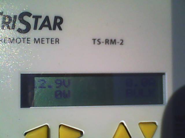
Last weekend I hit 99% PWM with 14.4 V on the meter and 111 watts.. then it went to BULK mode at 112 watts for the battery reading on the TS-45 meter..
Tommorrow with a good battery (and the sun and 80'F) I should have some real numbers (I hope).
Gonna let it run for 6 hours and see what happens..
Well I disagree, if the batteries are fully charged then even with just one panel the duty cycle should be near 0% meaning the batteries are not taking any current because they are full.
Agreed to some extent; you'll only see a proportional PWM number when you are delivering a significant amount of power. When the system is starting to regulate to reduce power you'll see a reduction of PWM below the Vin/Vout ratio. I wouldn't expect it to get close to zero unless the voltage setpoint gets significantly below the battery voltage though (i.e. heavy load, batteries fully charged, sudden reduction of load.) If your PWM value gives you a voltage even slightly below battery voltage you won't see any significant current flow.
Well I disagree, if the batteries are fully charged then even with just one panel the duty cycle should be near 0% meaning the batteries are not taking any current because they are full.
At the input of the CC you would see the voltage higher than Vmp of say 18 volts, and just ever so slightly below Voc of say 22 volts. So if th ePWM does go to 0% modulation you will see full Voc input because there is no current flowing. No current flowing in a panel with full sun light is Voltage Open Circuit aka Voc
Well I was at 20.7 VOC today.. then with both panels ON I was at 19.2 at the terminals inside the charge controller..
Well, 0% would require an infinite input voltage, so you won't get close to 0%. But if you are at 5 panels you might see a 20% duty cycle.
Well I disagree, if the batteries are fully charged then even with just one panel the duty cycle should be near 0% meaning the batteries are not taking any current because they are full.
At the input of the CC you would see the voltage higher than Vmp of say 18 volts, and just ever so slightly below Voc of say 22 volts. So if th ePWM does go to 0% modulation you will see full Voc input because there is no current flowing. No current flowing in a panel with full sun light is Voltage Open Circuit aka Voc
I'm going to try my setup again with a single panel and a GOOD battery (not the junky one that read 9.6 VDC this morning).. maybe I'll get more accurate numbers from it..
Thats why with 1 panel I was at 17.X VDC at the controller... then when I clicked #2 panel on the voltage jumped to 19.X VDC at the controller..
Why did the PWM % number go UP to 87% (from 53%) when I turned OFF 1 panel??
Actually fairly simple to explain:
With one panel, when the "switch" in the modulator was on, a limited amount of current was able to flow. So chopping that current by 87% gave the amount the battery needed
With two panels, the maximum current with the pulse on was higher, so it had to be turned off more of the time to get the same amount of current to the battery.
I1 x 87% ==> what the battery needed to hit target charge voltage.
(I1 + I2) x 53% ==> same current.
So when you measure the voltage at the input of a PWM controller and it is approx = to the battery voltage (about 1 volt higher), you know the PWM controller is at 100% duty cycle. As the battery aproaches full charge you will see the voltage from the panels rising up to Voc voltage of say 22 volts. When you reach Voc the PWM is at 0% duty cycle and there is no current flow at Voc.
Thats why with 1 panel I was at 17.X VDC at the controller... then when I clicked #2 panel on the voltage jumped to 19.X VDC at the controller..
I had 53% PWM with 2 panels ON.. then with just 1 panel ON it went to 87% PWM..
The watts and amps shown really didn't change except for a minute and then re-leveled..
Why did the PWM % number go UP to 87% (from 53%) when I turned OFF 1 panel??
OK EPSGUNNER I will try to explain what is going on with a PWM controller.
Think of a PWM controller as nothing more than a on/off switch. It regulates it output by turning the switch on/off called duty cycle from 0% (meaning the switch is always off disconnecting the panels form the batteries) to 100% where the panels are connected directly to the batteries. With me so far?
With a PWM controller the Input current = Output current and is the down fall of any serial regulator.
So lets say you have a 12 volt 100 AH battery that is 50% discharged, and you connect a 100 watt panel directly to the battery. A solar panel is a current source, not a voltage source. The spec on the panel is 18 volt Vmp and 5.55 Imp. When connected to a discharge battery the voltage of the panel is pulled down from 18 Vmp to match the battery voltage of around 12.1 volts and is supplying its constant current of 5.55 amps. Do the math 12.1 volts x 5.55 amps = 67 watts. You loose 33% of the panel power
So when you measure the voltage at th einput of a PWM controller and it is approx = to the battery voltage (about 1 volt higher), you know the PWM controller is at 100% duty cycle. As the battery aproaches full charge you will see the voltage from the panels rising up to Voc voltage of say 22 volts. When you reach Voc the PWM is at 0% duty cycle and there is no current flow at Voc.
FWIW use a MPPT controller with the same panel and battery at 50% DOD you will see the input voltage from th epanel @ 18 volts with 5.55 amps. On the output you would see 12.1 volts at 7.85 amps or 95 watts. Interesting huh? That is what a MPPT device does, it tracks Maximum Power Point of the panels.
Ok.. my take on this.. I have JUST hooked up just 2 of my 145w panels.. 18V and 8.05 AMP panels..
I get 20.7 at the combiner and 19.2 to the controller terminals(with a load drawing)..
Watch my video and see how the PWM jumps when I turn off 1 panel then turn it back on..
Each panels only making about 65-70 watts as my cloudy day... and the PWM is regulating the crap out of the incoming volts from the panels.. (this is because my battery is totally shot and was at 9.6VDC this morning when I started).
After 3 hours outside.. it said 4.X amps and 14.4 V going into the battery.. (didn't matter if it was just 1 panel on or 2..)
I turned off the panels at the end and got 13.6 volts and 0 amps for the battery..
I am guessing my PWM controller couldn't get an accurate read because of how it limits the OUTPUT to the battery and as the battery SHOWS full.. its really not..
I know the panels are good and CC is good.. I need to get a good battery that I can really test..


Leave a comment: