LifePO4 batteries for use with Midnite Classic 150?

Collapse
X
 
  • Time
  • Show
Clear All
new posts

  • karrak
    replied
    Sunking, are you deluded enough to really believe the garbage that you wrote in the last post or are you just throwing as much mud as possible in the hope that some of it will stick?

    I did not come here to harass you, I came here to put a counter viewpoint as someone who actually has an off grid LFP battery based power supply. As soon as it became apparent that I might actually know what I am talking about and couldn't be fobbed off you get nasty. The original discussion starts here solarpaneltalk.com/forum/off-grid-solar/batteries-energy-storage/lithium-ion/18054-lifep04-batteries-for-solar-bms?p=231297#post231297.

    I assume your statement "He clearly states he only came here to harass me on Bottom Balance" refers to this statement

    Thanks Paul, the only reason I am posting on the other forum is to counter the gospel according to Sunking and some of the things that he is saying that I think could easily lead some poor bastard to make a big mistake and wreck hundreds if not thousands of dollars worth of batteries.
    from here http://forums.energymatters.com.au/s...20.html#p46991. I will leave it to others to interpret what I said.

    As for recruiting other people, I assume you mean wb9k who happens to be the head of the warranty labs at A123. Here, solarpaneltalk.com/forum/off-grid-solar/batteries-energy-storage/lithium-ion/20597-mechanisms-that-decrease-the-lifespan-of-lithium-ion-batteries-and-how-to-avoid-them?p=247629#post247629, he states why he came to this forum.

    I'm not a regular poster here, but after similar encounters with Sunking on two other forums, I was approached by Simon to ask ask if he could quote one of my posts (which can be found on the battery technology forum at endless-sphere in a thread called "lithium balance--is it top, bottom, or middle?"). I said he could post with or without attribution, which is good because the moderators here have apparently forbidden attribution, which I find difficult to understand.
    As for the DIY EV forum shredding me, here is a link to the thread diyelectriccar.com/forums/showpost.php?p=713538&postcount=1 that I assume you are talking about, I post under the username simat on that forum.

    Simon

    Off grid 24V system, 6x190W Solar Panels, 32x90ah Winston LiFeYPO4 batteries installed April 2013
    BMS - Homemade Battery logger github.com/simat/BatteryMonitor
    Latronics 4kW Inverter, homemade MPPT controller
    Last edited by karrak; 06-05-2017, 07:23 PM.

    Leave a comment:


  • Sunking
    replied
    Originally posted by Mike90250
    If your posts on other forums are all taken at face value, then, they don't have the sharpest knives in the drawer,
    You got it Mike and 100% correct. Karrak came here for only one reason as he has admitted on this so called other forum. He clearly states he only came here to harass me on Bottom Balance. He asked for war, he got war and lost. If you remember Mike when Karak showed up and got ripped to pieces, Karrak went so far to go to other forums to recruit other people to come here and attack me. Did not work out so well for them.

    Mike you know I speak the truth. Given the fact Karrak came here only to attack me, recruited others to come here to attack me, SPAMS the site, has been banned twice already for giving bad/dangerous advice, and lost Link privileges; What more do you need to ban him permanently? He done everything he can to get banned and deserves it. He certainly cannot take a hint he is not welcomed here.

    FWIW he did go to a DIY EV forum where the members are very knowledgeable and sharp. Most members are engineers, technicians and scientist. They shredded Karrak to pieces with his hair brained ideas. .
    Last edited by Sunking; 06-03-2017, 12:18 PM.

    Leave a comment:


  • Mike90250
    replied
    Originally posted by karrak
    No, It is not me vs the world, it is me against the "alternative facts" that Sunking keeps stating. Don't have any problems and my posts are respected on the other forums that I post on... Simon
    If your posts on other forums are all taken at face value, then, they don't have the sharpest knives in the drawer, When I see your posts, and a couple words are in glowing neon as I skim it, it's like Whoa - Where is this harebrained idea from.

    Leave a comment:


  • karrak
    replied
    Originally posted by Mike90250

    Ah, so you are charging your magic batteries with AC, and that's where the problem of you vs world comes to a head. Impedance or Impudence ?
    No, It is not me vs the world, it is me against the "alternative facts" that Sunking keeps stating. Don't have any problems and my posts are respected on the other forums that I post on...

    Simon

    Off grid 24V system, 6x190W Solar Panels, 32x90ah Winston LiFeYPO4 batteries installed April 2013
    BMS - Homemade Battery logger github.com/simat/BatteryMonitor
    Latronics 4kW Inverter, homemade MPPT controller


    Leave a comment:


  • Sunking
    replied
    Originally posted by jflorey2
    No; he is referring to a Nyquist impedance plot of a lithium ion battery.
    I know what Nyquist Spectroscopy is, but has nothing to do with the topic of charging, nor is it exclusive to lithium batteries. It boils down to a Randles equivalent circuit so the user can determine battery health and predict how a small form factor battery battery will perform in a high frequency switch load like a cell phone. Non of which applies to charging a battery with DC current. All one really needs to know is AC Impedance will be lower than DC Resistance up to the point where the inductive characteristics coating on the plates. Completely irrelevant to the topic at hand.

    Where Impedance can be useful is battery monitor to make a WAG of battery health and SOC which no manufacturer has figured out how to do yet because it is to darn complicated and not fully understood. For solar use charging and discharging is completely meaningless jibber jabber. Yes you will get a slight dip and rise on a heavy discharge. Who cares on a 48 volt battery is less than 1 volt on Pb and less on Lithium. It means nothing to the user or be of any concern.

    Leave a comment:


  • Mike90250
    replied
    Well, I'll admit to being new to measuring battery impedance. I can see DC resistance, and how that can vary and change, but I've always considered impedance as C & L interaction with an AC signal, or DC pulsing fast enough to develop some reactance (almost like AC only slowly)
    I totally know about resistance and charge transport effects but never called them impedance.

    Leave a comment:


  • jflorey2
    replied
    Originally posted by Mike90250
    Ah, so you are charging your magic batteries with AC . . ..
    No; he is referring to a Nyquist impedance plot of a lithium ion battery. This is a method called impedance spectography, and tells you a lot about a battery. For example, pure resistances show up as fixed real impedances across all frequencies; charge transport (a big part of cell resistance) is frequency dependent and shows up at low frequencies.

    Ever load a battery and see a sudden voltage drop, followed by a slower one? You are seeing those two different mechanisms in play - one fast (resistance) one slow (charge transport.) Spec'ing resistance misses that effect; spec'ing impedance captures it.

    Leave a comment:


  • Sunking
    replied
    Originally posted by Mike90250

    Ah, so you are charging your magic batteries with AC, and that's where the problem of you vs world comes to a head. Impedance or Impudence ?
    Yeah I caught that to. Just proves Karrak is a fraud and dangerous. . Any damn fool knows batteries are charged with DC, and Resistance is the only factor. AC Impedance only comes into ply on digital or PWM switching Loads.
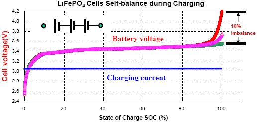
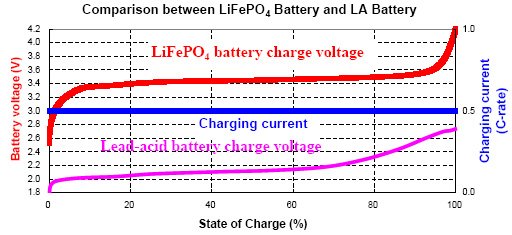
    Mostly Impedance is used by manufactures and users to determine battery health because it can be measured on an operational system where DC resistance cannot. When Impedance rises 50% from new condtion tells you your battery capacity has reached end of life. The impedance goes up as a result of the DC Resistance going up.


    Leave a comment:


  • Mike90250
    replied
    Originally posted by karrak
    .....Now to the glaring factual errors. The internal resistance of a battery or to be more correct the internal impedance,...
    Ah, so you are charging your magic batteries with AC, and that's where the problem of you vs world comes to a head. Impedance or Impudence ?

    Leave a comment:


  • Sunking
    replied
    Originally posted by karrak

    1. I used a 26650 cells from four different manufacturers. This shows that there is some variation in the chemistry of LiFePO4 cells, but the gross features are the same.

    2. Charging was done with a lab power supply, the voltage was set and the power supply current was limited to 1.6 amps. The battery would start out at 1.6 amps and when the voltage. This is a classic constant current-constant voltage charge.

    3. The battery was discharged at 2.5A rate, approximately 1C to 2.6 volts termination voltage.[/TD]


    As you can see the K series cells are at 99%SOC when charged to 3.4V, the G Series 98%, the A series 96% and the H series 96%, my Winston cells would be around ~99%SOC if floated at 3.4V.
    Karrak your reading comprhension flat out suks, and you do not know what your own terms mean. He did 9 charge/discharge test at 9 voltages. He started 3.0 volts and applied charge until the battery was SATURATED or fully Absorbed at 30 ma or C/73 . I know you do not know what that means, but it means until current all but stopped flowing and the battery floated at 3.0 volts. He then discharged it to measure the SOC.

    He repeated this step all the way up to 4.2 volts. Here is what your thick head cannot get wrapped around. You do not understand what Absorb phase is or when it starts. It is a PURE FUNCTION of OHMS LAW and nothing else. The voltage of a Charging Battery = OCV + [Ri x I]. So when charging at the Constant Current, and your battery voltage reaches 3.4 volts, the OCV is less than 3.4 volts. The battery OCV will not be 3.4 volts until charge current tapers down to 0 amps. Get your thick head wrapped around that On the 3.4, 3.5, and 3.6 volt test when he reached those voltages, the battery was only @ 60% SOC OCV. It took another 2 to 3 hours hours for the current to taper down from 1.6 amps to .030 amps to get the last 40% in. Has nothing to do with the battery chemistry. It has only to do with the battery Internal Resistance and Ohm's Law.

    It would be great if Solar Charge Controllers Absorb Phase could be controlled by current to switch from Absorb to Float. Fact is most are timed events. If they could be triggered by current you can stop charging at any SOC value you want for both LFP and Pb. If you want 100% SOC, it make no freaking difference if the battery is Pb or LFP, the parameters are the exact same. On a 4S LFP or 6S Pb set the Bulk/Absorb voltage to 14.4 volts, and switch to Float when Charge Current tapers down to 3 to 5% C.

    Since that is not possible, you have to use another algorithm on LFP batteries. You set Bulk = Absorb = Float for LFP batteries, and on a 4S LFP is going to be 13.6 to 13.8 volts. If your panel wattage is correct to provide a charge current of C/5 to C/2, your batteries will have time to SATURATE aka fully ABSORB to 3.4 vpc by the time the sun sets. If it doe snot fully saturate is not a problem because there is no requirement to fully charge LFP batteries like Pb.

    The fault with most any BMS is they are designed to charge LFP batteries to 100% SOC, and that is the last thing on earth you want to do. Extremely easy to do away with the BMS and get out of the Pb mentality thou must charge to 100% SOC to obtain the highest cycle life possible. Lithium is exact opposite where charging to 100% minimize cycle life. For LFP you want to operate between the knees of the charge/discharge curve, and that range is 3.0 and 3.4 volts per cell. On 4S is 12 to 13.6 volts.
    Last edited by Sunking; 05-26-2017, 11:51 AM.

    Leave a comment:


  • karrak
    replied
    Originally posted by Sunking
    In a Solar Application 13.6, 27.2, and 54.4 is the sweat spot. It yields up to 95% SOC capacity when fully saturated (100% Absorbed and charge current STOPS), and will double the cycle life of the battery by not going to 100%SOC of 3.6 volts. again using Karraks own source against him this graph from.
    ...
    There is little to be gained above 3.4 volts SATURATED aka Floated, CV, ABSORB or whatever you want to call it. Set your charger to 3.4 vpc and you are good. No risk or worries or meaningful capacity loss.
    The following is from the Powerstream website powerstream.com/lithium-phosphate-charge-voltage.htm.
    Method

    1. I used a 26650 cells from four different manufacturers. This shows that there is some variation in the chemistry of LiFePO4 cells, but the gross features are the same.
    2. Charging was done with a lab power supply, the voltage was set and the power supply current was limited to 1.6 amps. The battery would start out at 1.6 amps and when the voltage rose to the set limit, the current would drop. In most cases I waited until the current dropped to below 30mA. This is a classic constant current-constant voltage charge.

    3. The battery was discharged at 2.5A rate, approximately 1C to 2.6 volts termination voltage.
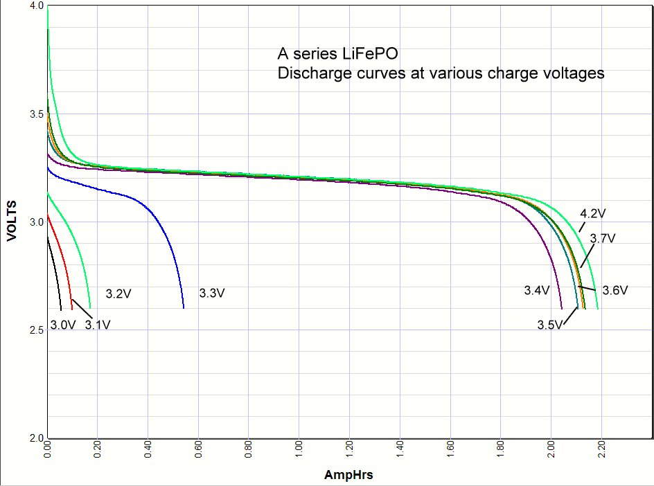
    Summary of tests, see discharge curves below
    Charge voltage Capacity at 3.65V 3.0V 3.1V 3.2V 3.3V 3.4V 3.5V 3.6V 3.7V 4.2V
    K Series 2249 mAH 48 mAH 93 174 691 2222 2232 2249 2249 2249 mAH
    Percentage of 3.65V capacity 2% 4% 8% 31% 99% 99% 100% 100% 100%
    G Series 2310 mAH 47 mAH 126 168 703 2257 2293 2309 2310 2324 mAH
    2% 5% 7% 30% 98% 99% 100% 100% 101%
    A Series 2136 mAH 57 mAH 101 173 543 2044 2127 2128 2136 2186 mAH
    3% 5% 8% 25% 96% 100% 100% 100% 103%
    H Series 2236 mAH 0 mAH 19 60 440 2153 2175 2196 2236 2238 mAH
    0% 1% 3% 20% 96% 97% 98% 100% 100%


    As you can see the K series cells are at 99%SOC when charged to 3.4V, the G Series 98%, the A series 96% and the H series 96%, my Winston cells would be around ~99%SOC if floated at 3.4V.

    Try charging an LFP cell at 3.4V and you start limiting the current at <80%SOC due to the internal resistance of the cell, leave it charging long enough and it will get to around 99% full. Charge at 3.45V, reduce the charge voltage at a current of C/20-C/50 to 3.35V and you end up with the same 98%-99%SOC in a shorter time. Using a float voltage of 3.35V rather than 3.4V should result in longer life for the cell.

    At 3.4 volts any BMS is just a waste of money and would never be used. In short if you operate between 3.0 to 3.4 Volts life is easy with no worries.
    Again from the Powerstream website

    3. Self balance
    Unlike the lead-acid battery, a number of LiFePO4 cells in a battery pack in series connection cannot balance each other during charging process. This is because the charge current stops flowing when the cell is full. This is why the LiFEPO4 packs need management boards.


    The load equipment and charger only know Ohm's Law of voltage. current, and resistance and it makes no difference what battery chemistry is used. They all charge the exact same way from the outside looking in. The electrons flowing don't care if they are moving Ions or chemical reactions around from one polarity to another. It is still current measured in AMPS either way. The formula for Amp Hours and Ohms Law does not change. For some reason Karrak thinks the Laws of Physics change.
    I agree that the load or charger will blindly follow Ohm's law. The voltage that the current is drawn from or supplied to the battery at is dependent on the chemical processes that are going on inside the battery and the bulk resistance of the different components of the battery. It is not the electrons that move ions or chemical reactions around, it is the voltage that causes the ions to flow or the chemical reactions to occur. The electrons flow is a result not a cause.

    Simon

    Leave a comment:


  • karrak
    replied
    Originally posted by Sunking
    Karrak you are proving you really do not get it. First Impedance has nothing to do with the discussion. it is pure DC resistance. That is just a diversion tactic you are trying to use. Impedance is used as a measurement for baseline reference for battery health, and modeling how a battery is going to perform on digital loads. DC resistance cannot be used on working systems without interruption in service, impedance can be used at any time.
    If you want to reduce this more accurate simplified battery model to this less accurate one
    that is fine by me.

    Your temperature argument is just another diversion without merit. All batteries are affected by temps, the most sensitive is lithium, so significantly most of them cannot be charged when cold.
    Where did I mention temperature?

    Your charts are pure rubbish. It is impossible for you to know what the SOC is at any given moment in time. To do that you would have to run a full capacity test to know what the actual capacity of a given cell is, start from a completely discharged battery at 2.5 volts, and graph Amp Hours vs voltage and current.
    Well if I can't do it then no one else can. Yes, I did do full capacity tests, actually I did several at each charge/discharge rate to make sure that the results were consistent. Interestingly the total capacity of the four year old 90Ah Winston cell that I tested was still ~90Ah. So much for your ranting that Winston batteries are a pile of **** and are only likely to last 2.5 to 5 years.

    But I will use one of your own sources against you to demonstrate you are full of crap. You very own Power Stream tells you under Conventional C/1 charge current:
    Sorry Sunking, that data agrees with my graphs, my graphs are at much lower charge rates (0.4C to 0.05C). If you look at my 3.45V graph you see that at 0.4C the absorb phase started at 78%. If you pushed the charge current up to 1C the absorb start point would be far lower than 78%, 60% seems very plausable.

    Resistance and Charge Rate is the Traffic Cop that limits any battery type charge type. Need more? Battery University will tell you the same thing. If you really wanted to know, it is super simple to find the information, I am not going to waste my time educating you.

    Clear as day, so zip it up, you do not know what you are talking about. The same process is true for any battery because when you reach the CV phase is function of Charge Rate and the battery Internal Resistance. If you understood basic electric fundamentals you would understand starting with Ohm's Law.
    I agree with you that the current going into the battery is dependent on the resistance of the battery, problem is that a portion of the resistance of the battery is caused by the chemical processes that are going on inside the battery. I am fairly sure that this resistance if nearly constant over the whole charging range of LFP batteries which gives the nice flat curve. It is not the case for LA batteries.


    Are you really that stupid and cannot grasp Ohm's Law? Yes P = IE, which means I = P/E. In the charging process on solar P changes with sun conditions, and thus varies unlike a stiff source with unlimited Power of the grid and commercial AC charger. If Power Input changes, so does charge current. As power goes up, current follows, as power goes down, current follows. Very simple 5th grade math. So technically a Solar Charger is Constant Power in Stag 1, butz the circuitry is a Constant Current Source. It will convert all available power into current up to the point of the chargers current limit rating. It is not hard to get your brain wrapped around if you understand basic principals of Ohms Law, current and voltage sources. Apparently they do not teach that where you live.
    Are you just trying to baffle everyone with this drivel. How can power go up and down and still be constant? sounds like newspeak to me. When I went to University a Constant Current Source was an idealised device that provides a constant current into a load (in this case a battery) regardless of the voltage across the load. I have even designed circuits with constant current sources in them. Surely a Constant Power Source provides constant power into a load regardless of the voltage across the load and current going into the load.

    Leave a comment:


  • Sunking
    replied

    Originally posted by jflorey2
    Yes they do, and everyone knows what they are talking about because people are familiar with those terms from working with lead acid batteries.

    Pilots still refer to stick and rudder skills. Doesn't mean that most aircraft have control sticks. But everyone knows what they mean.
    Carpenters still refer to Philips screws. Doesn't mean that the screws are actually Philips and not Pozidriv or Frearson. But everyone knows what they mean.

    Same thing here.
    Not from a general public and DIY POV. The public at general does not know that Bulk = Constant Current= Fast Charge, Boost Charge and the various terms used in the Industry. Ask John Doe and he will think each is different. So when they buy a Solar CC intended to be used on a Pb battery, may come away thinking it cannot be used on a Lithium battery which may or may not be true if the controllers voltage set points are fixed and not user settable. OTOH some controllers like Midnite Solar and Morningstar do have models the user can set voltages to what is required for Lithium. If the manufacture does that you can turn the Controller into what you want to call a CC/CV charger by setting Bulk = Absorb = Float. You and I know that, but the mass public does not know that. Karrak is a good example of not comprehending what is really going on. Any charger is DUMB and does not know what battery type it is connected to. The chemistry inside is irrelevant to the charger. The only difference is how you terminate the charge and what algorithm you use. With LFP cells used in 4S, 8S, 12S... are drop in replacements for Pb. If you buy say a 12 volt LFP battery (4S) replacement for your vehicle, no modifications are needed to the vehicle charging system. They will work with any alternator voltage from as low as 13.6 volts up to 14.6 volts.

    In a Solar Application 13.6, 27.2, and 54.4 is the sweat spot. It yields up to 95% SOC capacity when fully saturated (100% Absorbed and charge current STOPS), and will double the cycle life of the battery by not going to 100%SOC of 3.6 volts. again using Karraks own source against him this graph from Power Stream demonstrates clearly where users want to operate. There is little to be gained above 3.4 volts SATURATED aka Floated, CV, ABSORB or whatever you want to call it. Set your charger to 3.4 vpc and you are good. No risk or worries or meaningful capacity loss. Power stream even goes on the say:

    Commentary: It looks like the magic number is around 3.3 volts. Below that you don't have significant charging, above that you do. A lithium iron phosphate battery doesn't care if it is never fully charged, so if all you have available is 3.3 volts and you don't mind the loss in capacity you could use the 3.3 volts. This opens up new possibility for a simple but very long life backup battery
    At 3.4 volts any BMS is just a waste of money and would never be used. In short if you operate between 3.0 to 3.4 Volts life is easy with no worries. Completely compatible with Pb. On a 4S LFP is 12 to 13.6 volts. Set your charger to 13/6 volts, and your Inverter LVD to 12 volts and relax. Ohm's Law and common sense will take car of the rest. The load equipment and charger only know Ohm's Law of voltage. current, and resistance and it makes no difference what battery chemistry is used. They all charge the exact same way from the outside looking in. The electrons flowing don't care if they are moving Ions or chemical reactions around from one polarity to another. It is still current measured in AMPS either way. The formula for Amp Hours and Ohms Law does not change. For some reason Karrak thinks the Laws of Physics change.


    Anyway Jeff if this was a Professional Forum, I would agree with you. But his is DIY forum and terminology has to be explained out in great detail so people like Karrak can understand. Even then they may not get it.
    Last edited by Sunking; 05-25-2017, 03:26 PM.

    Leave a comment:


  • jflorey2
    replied
    Originally posted by Sunking
    No Sir it is not specific to Pb. You didn't read any links now did you?. Manufactures chargers made for LFP uses the terms Bulk and Absorb.
    Yes they do, and everyone knows what they are talking about because people are familiar with those terms from working with lead acid batteries.

    Pilots still refer to stick and rudder skills. Doesn't mean that most aircraft have control sticks. But everyone knows what they mean.
    Carpenters still refer to Philips screws. Doesn't mean that the screws are actually Philips and not Pozidriv or Frearson. But everyone knows what they mean.

    Same thing here.

    Leave a comment:


  • Sunking
    replied
    Karrak you are proving you really do not get it. First Impedance has nothing to do with the discussion. it is pure DC resistance. That is just a diversion tactic you are trying to use. Impedance is used as a measurement for baseline reference for battery health, and modeling how a battery is going to perform on digital loads. DC resistance cannot be used on working systems without interruption in service, impedance can be used at any time.

    Your temperature argument is just another diversion without merit. All batteries are affected by temps, the most sensitive is lithium, so significantly most of them cannot be charged when cold.

    Your charts are pure rubbish. It is impossible for you to know what the SOC is at any given moment in time. To do that you would have to run a full capacity test to know what the actual capacity of a given cell is, start from a completely discharged battery at 2.5 volts, and graph Amp Hours vs voltage and current.

    But I will use one of your own sources against you to demonstrate you are full of crap. You very own Power Stream tells you under Conventional C/1 charge current:

    During the conventional lithium ion charging process, a conventional Li-ion Battery containing lithium iron phosphate (LiFePO4) needs two steps to be fully charged: step 1 uses constant current (CC) to reach about 60% State of Charge (SOC); step 2 takes place when charge voltage reaches 3.65V per cell, which is the upper limit of effective charging voltage. Turning from constant current (CC) to constant voltage (CV) means that the charge current is limited by what the battery will accept at that voltage, so the charging current tapers down asymptotically, just as a capacitor charged through a resistor will reach the final voltage asymptotically.

    To put a clock to the process, step 1 (60%SOC) needs about one hour and the step 2 (40%SOC) needs another two hours.
    Resistance and Charge Rate is the Traffic Cop that limits any battery type charge type. Need more? Battery University will tell you the same thing. If you really wanted to know, it is super simple to find the information, I am not going to waste my time educating you.

    Increasing the charge current does not hasten the full-charge state by much. Although the battery reaches the voltage peak quicker, the saturation charge will take longer accordingly. With higher current, Stage 1 is shorter but the saturation during Stage 2 will take longer.
    Clear as day, so zip it up, you do not know what you are talking about. The same process is true for any battery because when you reach the CV phase is function of Charge Rate and the battery Internal Resistance. If you understood basic electric fundamentals you would understand starting with Ohm's Law.

    Power = Voltage x Current, how can you have constant power if the current is variable when charging from solar?

    For LFP batteries, charging from solar is not the same as charging from a constant current charger. With a constant current charger we can charge at say ~C/4 (0.25C) and terminate the charge at 3.45 volts and have a predictable ~90%SOC. With solar we could have anything from ~90%SOC to ~99%SOC due to the variable nature of the power coming from the solar panels. If you are bottom balancing with no BMS this could have disastrous consequences.
    Are you really that stupid and cannot grasp Ohm's Law? Yes P = IE, which means I = P/E. In the charging process on solar P changes with sun conditions, and thus varies unlike a stiff source with unlimited Power of the grid and commercial AC charger. If Power Input changes, so does charge current. As power goes up, current follows, as power goes down, current follows. Very simple 5th grade math. So technically a Solar Charger is Constant Power in Stag 1, butz the circuitry is a Constant Current Source. It will convert all available power into current up to the point of the chargers current limit rating. It is not hard to get your brain wrapped around if you understand basic principals of Ohms Law, current and voltage sources. Apparently they do not teach that where you live.

    This is one reason I hit you so hard. You are pretender which makes you a fraud. You do not know basic electrical fundamentals. You do not even understand day 1 course material Ohms Law. You further prove your ignorance with dangerous advice in which you have been banned twice for doing so. Why they let you come back baffles me.
    Last edited by Sunking; 05-25-2017, 03:17 PM.

    Leave a comment:

Working...